SFI SYSTEM (w/ EGR System), Diagnostic DTC:P0300, P0301, P0302, P0303, P0304

| DTC Code | DTC Name |
|---|---|
| P0300 | Random / Multiple Cylinder Misfire Detected |
| P0301 | Cylinder 1 Misfire Detected |
| P0302 | Cylinder 2 Misfire Detected |
| P0303 | Cylinder 3 Misfire Detected |
| P0304 | Cylinder 4 Misfire Detected |
DESCRIPTION
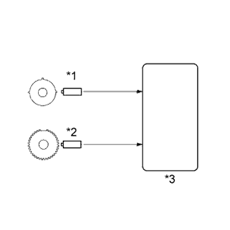
| *1 | Camshaft Position Sensor |
| *2 | Crankshaft Position Sensor |
| *3 | ECM |
When the engine misfires, high concentrations of hydrocarbons (HC) enter the exhaust gas. High HC concentration levels can cause an increase in exhaust emission levels. Extremely high concentrations of HC can also cause increases in the three-way catalytic converter temperature, which may cause damage to the three-way catalytic converter. To prevent this increase in emissions and to limit the possibility of thermal damage, the ECM monitors the misfire rate. When the temperature of the three-way catalytic converter reaches the point of thermal degradation, the ECM blinks the MIL. To monitor misfires, the ECM uses both the Camshaft Position (CMP) sensor and the Crankshaft Position (CKP) sensor. The camshaft position sensor is used to identify any misfiring cylinders and the crankshaft position sensor is used to measure variations in the crankshaft rotation speed. Misfires are counted when the crankshaft rotation speed variations exceed predetermined thresholds. If the misfire count exceeds the threshold levels, and could cause emission control system performance deterioration, the ECM illuminates the MIL and sets a DTC.
| DTC No. | DTC Detection Condition | Trouble Area |
|---|---|---|
| P0300 | When one of following conditions below is detected (2 trip detection logic):
|
|
| P0301 P0302 P0303 P0304 |
When one of following conditions below is detected (2 trip detection logic):
|
When DTCs for misfiring cylinders are randomly set, but DTC P0300 is not set, it indicates that misfires have been detected in different cylinders at different times. DTC P0300 is only set when several misfiring cylinders are detected at the same time.
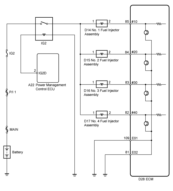
WIRING DIAGRAM
CONFIRMATION DRIVING PATTERN
-
Connect the intelligent tester to the DLC3.
-
Turn the power switch on (IG).
-
Turn the tester on.
-
Record the DTC(s) and freeze frame data.
-
Put the engine in inspection mode Click here.
-
Using the tester, switch the ECM from normal mode to check mode Click here.
-
Read the misfire counts of each cylinder, Cylinder #1 Misfire Count to Cylinder #4 Misfire Count, with the engine idling. If any misfire count is displayed, skip the following confirmation driving pattern.
-
Drive the vehicle several times with the conditions, such as engine speed and engine load, shown in Misfire RPM and Misfire Load in the Data List.
Tech Tips
In order to store misfire DTCs, it is necessary to operate the vehicle for the period of time shown in the table below, using the Misfire RPM and Misfire Load in the Data List.
Engine Speed Duration Idling 4 minutes or more 1000 4 minutes and 30 seconds or more 2000 2 minutes and 30 seconds or more 3000 1 minute and 30 seconds or more -
Check whether misfires have occurred by checking DTCs and freeze frame data.
Tech Tips
Do not turn the power switch off until the stored DTC(s) and freeze frame data have been recorded. When the ECM returns to normal mode (default), the stored DTC(s), freeze frame data and other data will be cleared.
-
Record the DTC(s), freeze frame data and misfire counts.
-
Turn the power switch off and wait for at least 5 seconds.
INSPECTION PROCEDURE
Tech Tips
-
If any DTCs other than misfire DTCs are output, troubleshoot those DTCs first.
-
Read freeze frame data using the intelligent tester. The ECM records vehicle and driving condition information as freeze frame data the moment a DTC is stored. When troubleshooting, freeze frame data can be helpful in determining whether the vehicle was running or stopped, whether the engine was warmed up or not, whether the air fuel ratio was lean or rich, as well as other data recorded at the time of a malfunction.
-
If the misfire does not recur when the vehicle is brought to the workshop, reproduce the conditions stored in the ECM as freeze frame data.
-
If the misfire still cannot be reproduced even though the conditions stored in the ECM as freeze frame data have been reproduced, one of the following factors is considered to be a possible cause of the problem:
-
There was insufficient fuel in the tank.
-
Improper fuel is used.
-
The spark plugs have been contaminated.
-
The problem requires further diagnosis.
-
After finishing repairs, check the misfire counts of the cylinders Cylinder #1 Misfire Count to Cylinder #4 Misfire Count.
-
Be sure to confirm that no misfiring cylinder DTCs are set again by conducting the confirmation driving pattern after finishing repairs.
-
When one of Short FT #1or Long FT #1 in the freeze frame data is outside the range of +/-20%, the air fuel ratio may be Rich (-20% or less) or Lean (+20% or more).
-
When the Coolant Temp in the freeze frame data is less than 75°C (167°F), the misfire has occurred only while warming up the engine.
-
An extremely imbalanced drive wheel which causes body vibration may cause misfire DTCs detection.
PROCEDURE
-
CHECK ANY OTHER DTCS OUTPUT (IN ADDITION TO MISFIRE DTCS)
-
Connect the intelligent tester to the DLC3.
-
Turn the power switch on (IG).
-
Turn the tester on.
-
Enter the following menus: Powertrain / Engine and ECT / DTC.
-
Read the DTCs.
Tech Tips
Write down the indicated DTCs.
Result Result Proceed to DTC P0300, P0301, P0302, P0303 and/or P0304 are output A DTC P0300, P0301, P0302, P0303 and/or P0304 and other DTCs are output B Tech Tips
If any DTCs other than P0300, P0301, P0302, P0303 and/or P0304 are output, troubleshoot those DTCs first.
B 
GO TO DTC CHART Click here
A 
-
-
CHECK PCV HOSE (HOSE CONNECTIONS)
-
Check the PCV hose connections.
OK PCV hose is correctly connected and is not damaged.
NG
REPAIR OR REPLACE PCV HOSE
OK
-
-
READ VALUE USING INTELLIGENT TESTER (MISFIRE RPM AND MISFIRE LOAD)
-
Connect the intelligent tester to the DLC3.
-
Turn the power switch on (IG).
-
Turn the tester on.
-
Enter the following menus: Powertrain / Engine and ECT / Data List / Misfire RPM and Misfire Load.
-
Read and note the Misfire RPM and Misfire Load values.
Tech Tips
The Misfire RPM and Misfire Load values indicate the vehicle conditions under which the misfire occurred.
NEXT
-
-
READ VALUE USING INTELLIGENT TESTER (CYLINDER #1 MISFIRE COUNT, #2, #3 AND #4)
-
Connect the intelligent tester to the DLC3.
-
Turn the power switch on (IG).
-
Turn the tester on.
-
Put the engine in inspection mode Click here.
-
Enter the following menus: Powertrain / Engine and ECT / Data List / Cylinder #1 (to #4) Misfire Count.
-
Read each value for Cylinder #1 (to #4) Misfire Count displayed on the intelligent tester. If no misfire counts occur in any cylinders, perform steps [A] and [B], and then check the misfire counts again.
-
Drive the vehicle with the Misfire RPM and Misfire Load noted in the read value using the intelligent tester (Misfire RPM and Misfire Load) procedures above [A].
-
Read Cylinder #1 (to #4) Misfire Count or the DTCs displayed on the tester [B].
Result Misfire Count Proceed to Most misfires occur in only 1 or 2 cylinders A 3 cylinders or more have equal misfire counts B Tech Tips
-
If the freeze frame data record of the engine coolant temperature is below 75°C (167°F), it may only be possible to detect the misfire when the engine is cold.
-
If the freeze frame data record of the Engine Run Time is below 120 seconds, the misfire may be detected immediately after the engine is started.
-
B 
CHECK INTAKE SYSTEM Click here
A
-
-
INSPECT SPARK PLUG
-
Remove the ignition coil assembly and the spark plug of the misfiring cylinder.
-
Check the electrode for carbon deposits.
Recommended Spark Plug Manufacturer Product DENSO SC20HR11 -
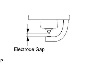
Measure the spark plug electrode gap.
Maximum Electrode Gap for Used Spark Plug 1.3 mm (0.0512 in.) If the gap is greater than the maximum, replace the spark plug.
Electrode Gap for New Spark Plug 1.0 to 1.1 mm (0.0394 to 0.0433 in.) -
Reinstall the ignition coil assembly and spark plug.
NG
REPLACE SPARK PLUG Click here
OK
-
-
CHECK FOR SPARK (SPARK TEST)
-
Perform spark test Click here.
CAUTION:
Always disconnect all fuel injector assembly connectors.
Note
Do not crank the engine for more than 2 seconds.
OK Spark jumps across electrode gap.
NG
CHANGE TO KNOWN GOOD SPARK PLUG AND CHECK SPARK OF MISFIRING CYLINDER Click here
OK
-
-
CHECK CYLINDER COMPRESSION PRESSURE OF MISFIRING CYLINDER
-
Measure the cylinder compression pressure of the misfiring cylinder Click here.
NG
CHECK ENGINE TO DETERMINE CAUSE OF LOW COMPRESSION
OK
-
-
CHECK FUEL INJECTOR ASSEMBLY (POWER SOURCE)
-
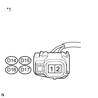
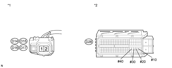
Text in Illustration *1 Front view of wire harness connector
(to Fuel Injector Assembly)
Disconnect the fuel injector assembly connectors.
-
Turn the power switch on (IG).
-
Measure the voltage according to the value(s) in the table below.
Standard Voltage Tester Connection Switch Condition Specified Condition D14-1 - Body ground Power switch on (IG) 11 to 14 V D15-1 - Body ground Power switch on (IG) 11 to 14 V D16-1 - Body ground Power switch on (IG) 11 to 14 V D17-1 - Body ground Power switch on (IG) 11 to 14 V -
Reconnect the fuel injector assembly connectors.
NG
CHECK FUEL INJECTOR CIRCUIT Click here
OK
-
-
CHECK HARNESS AND CONNECTOR (FUEL INJECTOR ASSEMBLY - ECM)
-
Disconnect the fuel injector assembly connectors.
-
Disconnect the ECM connector.
-
Measure the resistance according to the value(s) in the table below.
Standard Resistance (Check for Open) Tester Connection Condition Specified Condition D14-2 - D28-85 (#10) Always Below 1 Ω D15-2 - D28-84 (#20) Always Below 1 Ω D16-2 - D28-83 (#30) Always Below 1 Ω D17-2 - D28-82 (#40) Always Below 1 Ω Standard Resistance (Check for Short) Tester Connection Condition Specified Condition D14-2 or D28-85 (#10) - Body ground Always 10 Ω or higher D15-2 or D28-84 (#20) - Body ground Always 10 Ω or higher D16-2 or D28-83 (#30) - Body ground Always 10 Ω or higher D17-2 or D28-82 (#40) - Body ground Always 10 Ω or higher Text in Illustration *1 Front view of wire harness connector
(to Fuel Injector Assembly)
*2 Front view of wire harness connector
(to ECM)
-
Reconnect the fuel injector assembly connectors.
-
Reconnect the ECM connector.
NG
REPAIR OR REPLACE HARNESS OR CONNECTOR (FUEL INJECTOR ASSEMBLY - ECM)
OK
-
-
INSPECT ECM TERMINAL OF MISFIRING CYLINDER (#10, #20, #30 AND/OR #40 VOLTAGE)
-
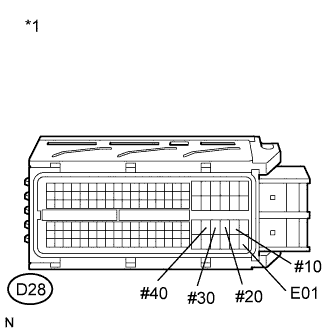
Text in Illustration *1 Front view of wire harness connector
(to ECM)
Disconnect the ECM connector.
-
Turn the power switch on (IG).
-
Measure the voltage according to the value(s) in the table below.
Standard Voltage Tester Connection Switch Condition Specified Condition D28-85 (#10) - D28-109 (E01) Power switch on (IG) 11 to 14 V D28-84 (#20) - D28-109 (E01) Power switch on (IG) 11 to 14 V D28-83 (#30) - D28-109 (E01) Power switch on (IG) 11 to 14 V D28-82 (#40) - D28-109 (E01) Power switch on (IG) 11 to 14 V -
Reconnect the ECM connector.
NG
REPAIR OR REPLACE HARNESS OR CONNECTOR (ECM - BODY GROUND)
OK
-
-
CHECK FUEL INJECTOR ASSEMBLY OF MISFIRING CYLINDER
-
Check the fuel injector assembly injection (whether fuel volume is high or low, and whether injection pattern is poor) Click here.
NG
REPLACE FUEL INJECTOR ASSEMBLY Click here
OK
-
-
CHECK INTAKE SYSTEM
-
Check the intake system for vacuum leaks Click here.
OK No leaks in intake system.
NG
REPAIR OR REPLACE INTAKE SYSTEM
OK
-
-
INSPECT MASS AIR FLOW METER SUB-ASSEMBLY
-
Inspect the mass air flow meter sub-assembly Click here.
NG
REPLACE MASS AIR FLOW METER SUB-ASSEMBLY Click here
OK
-
-
CHECK FUEL PRESSURE
-
Check the fuel pressure Click here.
NG
CHECK FUEL LINE Click here
OK
-
-
READ VALUE USING INTELLIGENT TESTER (COOLANT TEMP)
-
Connect the intelligent tester to the DLC3.
-
Turn the power switch on (IG).
-
Turn the tester on.
-
Enter the following menus: Powertrain / Engine and ECT / Data List / Coolant Temp.
-
Read the Data List twice, when the engine is both cold and warmed up.
Standard value With cold engine: Same as ambient air temperature. With warm engine: 80 to 100°C (176 to 212°F).
NG
REPLACE ENGINE COOLANT TEMPERATURE SENSOR Click here
OK
-
-
ADJUST VALVE TIMING
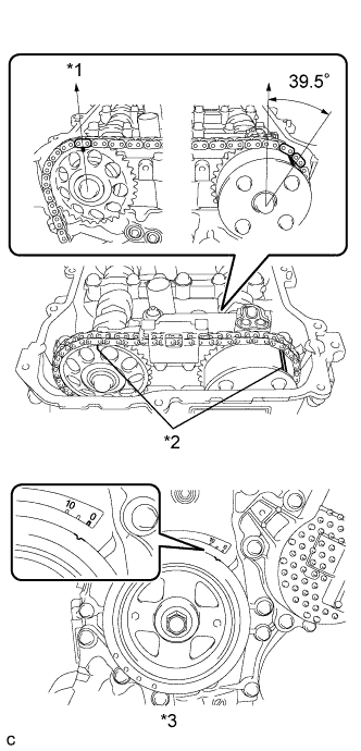
Text in Illustration *1 Top *2 Alignment Mark *3 No. 1 Cylinder at TDC Compression Tech Tips
There are no marks on the cylinder head to match-up for the purpose of checking valve timing. Valve timing can only be inspected by lining up the colored plates on the timing chain with the marks on the pulleys. It may be necessary to remove and reinstall the chain to match-up the alignment marks Click here.
NEXT
-
CHECK WHETHER DTC OUTPUT RECURS (P0300, P0301, P0302, P0303 OR P0304)
-
Connect the intelligent tester to the DLC3.
-
Turn the power switch on (IG).
-
Turn the tester on.
-
Perform confirmation driving pattern.
-
Enter the following menus: Powertrain / Engine and ECT / DTC / Pending.
-
Read the pending DTCs.
Result Result Proceed to DTC P0300, P0301, P0302, P0303 or P0304 is output A DTC is not output B
B
END
A
-
-
PERFORM ACTIVE TEST USING INTELLIGENT TESTER (CONTROL THE EGR STEP POSITION)
-
Connect the intelligent tester to the DLC3.
-
Turn the power switch on (IG).
-
Turn the tester on.
-
Put the engine in inspection mode (maintenance mode) Click here.
-
Start the engine and warm it up until the engine coolant temperature reaches 75°C (167°F) or higher.
Tech Tips
The A/C switch and all accessory switches should be off.
-
Enter the following menus: Powertrain / Engine and ECT / Active Test / Control the EGR Step Position / Data List / All Data / Throttle Idle Position and MAP.
-
Confirm that the Throttle Idle Position is ON and check the MAP value in the Data List while performing the Active Test.
Note
-
Do not leave the EGR valve open for 10 seconds or more during the Active Test.
-
Be sure to return the EGR valve to step 0 when the Active Test is completed.
-
Do not open the EGR valve 30 steps or more during the Active Test.
OK MAP change in response to EGR step position when Throttle Idle Position is ON in Data List. Standard - EGR Step Position (Active Test) 0 Steps 0 to 30 Steps MAP
(Data List)
(EGR valve is fully closed) MAP value is at least +10 kPa (75 mmHg) higher than when EGR valve is fully closed Tech Tips
-
While performing the Active Test, if the increase in the value of MAP is small, the EGR valve assembly may be a malfunctioning.
-
Even if the EGR valve assembly is malfunctioning, rough idling or an increase in the value of MAP may occur while performing the Active Test. However, the amount that the value of MAP increases will be smaller than normal.
Result Result Proceed to Outside of standard range A Within standard range B -
B
REPLACE ECM Click here
A
-
-
INSPECT EGR VALVE ASSEMBLY
-
Remove the EGR valve assembly Click here.
-
Check if the EGR valve is stuck open.
OK EGR valve is tightly closed. -
Reinstall the EGR valve assembly Click here.
NG
REPLACE EGR VALVE ASSEMBLY Click here
OK
-
-
REPLACE ECM
-
Replace the ECM Click here.
NEXT
-
-
CONFIRM WHETHER MALFUNCTION HAS BEEN SUCCESSFULLY REPAIRED
-
Connect the intelligent tester to the DLC3.
-
Turn the power switch on (IG).
-
Turn the tester on.
-
Clear the DTC Click here.
-
Turn the power switch off and wait for 30 seconds.
-
Turn the power switch on (IG) and turn the tester on.
-
Put the engine in inspection mode Click here.
-
Start the engine and warm it up.
-
Drive the vehicle in accordance with the driving pattern described in the Confirmation Driving Pattern.
-
Enter the following menus: Powertrain / Engine and ECT / Utility / All Readiness.
-
Input the DTCs: P0300, P0301, P0302, P0303, P0304.
-
Check the DTCs judgment result.
NEXT 
END
-
-
CHECK INTAKE SYSTEM
-
Check the intake system for vacuum leaks Click here.
OK No leaks in intake system.
NG
REPAIR OR REPLACE INTAKE SYSTEM
OK
-
-
INSPECT MASS AIR FLOW METER SUB-ASSEMBLY
-
Inspect the mass air flow meter sub-assembly Click here.
NG
REPLACE MASS AIR FLOW METER SUB-ASSEMBLY Click here
OK
-
-
CHECK FUEL PRESSURE
-
Check the fuel pressure Click here.
NG
CHECK FUEL LINE Click here
OK
-
-
READ VALUE USING INTELLIGENT TESTER (COOLANT TEMP)
-
Connect the intelligent tester to the DLC3.
-
Turn the power switch on (IG).
-
Turn the tester on.
-
Enter the following menus: Powertrain / Engine and ECT / Data List / Coolant Temp.
-
Read the Data List twice, when the engine is both cold and warmed up.
Standard value With cold engine: Same as ambient air temperature. With warm engine: 80 to 100°C (176 to 212°F).
NG
REPLACE ENGINE COOLANT TEMPERATURE SENSOR Click here
OK
-
-
PERFORM ACTIVE TEST USING INTELLIGENT TESTER (CONTROL THE EGR STEP POSITION)
-
Connect the intelligent tester to the DLC3.
-
Turn the power switch on (IG).
-
Turn the tester on.
-
Put the engine in inspection mode (maintenance mode) Click here.
-
Start the engine and warm it up until the engine coolant temperature reaches 75°C (167°F) or higher.
Tech Tips
The A/C switch and all accessory switches should be off.
-
Enter the following menus: Powertrain / Engine and ECT / Active Test / Control the EGR Step Position / Data List / All Data / Throttle Idle Position and MAP.
-
Confirm that the Throttle Idle Position is ON and check the MAP value in the Data List while performing the Active Test.
Note
-
Do not leave the EGR valve open for 10 seconds or more during the Active Test.
-
Be sure to return the EGR valve to step 0 when the Active Test is completed.
-
Do not open the EGR valve 30 steps or more during the Active Test.
OK MAP change in response to EGR step position when Throttle Idle Position is ON in Data List. Standard - EGR Step Position (Active Test) 0 Steps 0 to 30 Steps MAP
(Data List)
(EGR valve is fully closed) MAP value is at least +10 kPa (75 mmHg) higher than when EGR valve is fully closed Tech Tips
-
While performing the Active Test, if the increase in the value of MAP is small, the EGR valve assembly may be a malfunctioning.
-
Even if the EGR valve assembly is malfunctioning, rough idling or an increase in the value of MAP may occur while performing the Active Test. However, the amount that the value of MAP increases will be smaller than normal.
Result Result Proceed to Outside of standard range A Within standard range B -
B
INSPECT SPARK PLUG Click here
A
-
-
INSPECT EGR VALVE ASSEMBLY
-
Remove the EGR valve assembly Click here.
-
Check if the EGR valve is stuck open.
OK EGR valve is tightly closed. -
Reinstall the EGR valve assembly Click here.
NG
REPLACE EGR VALVE ASSEMBLY Click here
OK
-
-
INSPECT SPARK PLUG
-
Remove the ignition coil assembly and the spark plug of the misfiring cylinder.
-
Check the electrode for carbon deposits.
Recommended Spark Plug Manufacturer Product DENSO SC20HR11 -
Measure the spark plug electrode gap.
Maximum Electrode Gap for Used Spark Plug 1.3 mm (0.0512 in.) If the gap is greater than the maximum, replace the spark plug.
Electrode Gap for New Spark Plug 1.0 to 1.1 mm (0.0394 to 0.0433 in.) -
Reinstall the ignition coil assembly and spark plug.
NG
REPLACE SPARK PLUG Click here
OK
-
-
CHECK FOR SPARK (SPARK TEST)
-
Perform spark test Click here.
CAUTION:
Always disconnect all fuel injector assembly connectors.
Note
Do not crank the engine for more than 2 seconds.
OK Spark jumps across electrode gap.
NG
CHANGE TO KNOWN GOOD SPARK PLUG AND CHECK SPARK OF MISFIRING CYLINDER Click here
OK
-
-
CHECK CYLINDER COMPRESSION PRESSURE OF MISFIRING CYLINDER
-
Measure the cylinder compression pressure of the misfiring cylinder Click here.
NG
CHECK ENGINE TO DETERMINE CAUSE OF LOW COMPRESSION
OK
-
-
CHECK FUEL INJECTOR ASSEMBLY (POWER SOURCE)
-
Text in Illustration *1 Front view of wire harness connector
(to Fuel Injector Assembly)
Disconnect the fuel injector assembly connectors.
-
Turn the power switch on (IG).
-
Measure the voltage according to the value(s) in the table below.
Standard Voltage Tester Connection Switch Condition Specified Condition D14-1 - Body ground Power switch on (IG) 11 to 14 V D15-1 - Body ground Power switch on (IG) 11 to 14 V D16-1 - Body ground Power switch on (IG) 11 to 14 V D17-1 - Body ground Power switch on (IG) 11 to 14 V -
Reconnect the fuel injector assembly connectors.
NG
CHECK FUEL INJECTOR CIRCUIT Click here
OK
-
-
CHECK HARNESS AND CONNECTOR (FUEL INJECTOR ASSEMBLY- ECM)
-
Disconnect the fuel injector assembly connectors.
-
Disconnect the ECM connector.
-
Measure the resistance according to the value(s) in the table below.
Standard Resistance (Check for Open) Tester Connection Condition Specified Condition D14-2 - D28-85 (#10) Always Below 1 Ω D15-2 - D28-84 (#20) Always Below 1 Ω D16-2 - D28-83 (#30) Always Below 1 Ω D17-2 - D28-82 (#40) Always Below 1 Ω Standard Resistance (Check for Short) Tester Connection Condition Specified Condition D14-2 or D28-85 (#10) - Body ground Always 10 Ω or higher D15-2 or D28-84 (#20) - Body ground Always 10 Ω or higher D16-2 or D28-83 (#30) - Body ground Always 10 Ω or higher D17-2 or D28-82 (#40) - Body ground Always 10 Ω or higher Text in Illustration *1 Front view of wire harness connector
(to Fuel Injector Assembly)
*2 Front view of wire harness connector
(to ECM)
-
Reconnect the fuel injector assembly connectors.
-
Reconnect the ECM connector.
NG
REPAIR OR REPLACE HARNESS OR CONNECTOR (FUEL INJECTOR ASSEMBLY - ECM)
OK
-
-
INSPECT ECM TERMINAL OF MISFIRING CYLINDER (#10, #20, #30 AND/OR #40 VOLTAGE)
-
Text in Illustration *1 Front view of wire harness connector
(to ECM)
Disconnect the ECM connector.
-
Turn the power switch on (IG).
-
Measure the voltage according to the value(s) in the table below.
Standard Voltage Tester Connection Switch Condition Specified Condition D28-85 (#10) - D28-109 (E01) Power switch on (IG) 11 to 14 V D28-84 (#20) - D28-109 (E01) Power switch on (IG) 11 to 14 V D28-83 (#30) - D28-109 (E01) Power switch on (IG) 11 to 14 V D28-82 (#40) - D28-109 (E01) Power switch on (IG) 11 to 14 V -
Reconnect the ECM connector.
NG
REPAIR OR REPLACE HARNESS OR CONNECTOR (ECM - BODY GROUND)
OK
-
-
CHECK FUEL INJECTOR ASSEMBLY OF MISFIRING CYLINDER
-
Check the fuel injector assembly injection (whether fuel volume is high or low, and whether injection pattern is poor) Click here.
NG
REPLACE FUEL INJECTOR ASSEMBLY Click here
OK
-
-
ADJUST VALVE TIMING
Text in Illustration *1 Top *2 Alignment Mark *3 No. 1 Cylinder at TDC Compression Tech Tips
There are no marks on the cylinder head to match-up for the purpose of checking valve timing. Valve timing can only be inspected by lining up the colored plates on the timing chain with the marks on the pulleys. It may be necessary to remove and reinstall the chain to match-up the alignment marks Click here.
NEXT
-
CHECK WHETHER DTC OUTPUT RECURS (DTC P0300, P0301, P0302, P0303 OR P0304)
-
Connect the intelligent tester to the DLC3.
-
Turn the power switch on (IG).
-
Turn the tester on.
-
Perform confirmation driving pattern.
-
Enter the following menus: Powertrain / Engine and ECT / DTC / Pending.
-
Read the pending DTCs.
Result Result Proceed to DTC P0300, P0301, P0302, P0303 or P0304 is output A DTC is not output B
B
END
A
-
-
REPLACE ECM
-
Replace the ECM Click here.
NEXT
-
-
CONFIRM WHETHER MALFUNCTION HAS BEEN SUCCESSFULLY REPAIRED
-
Connect the intelligent tester to the DLC3.
-
Turn the power switch on (IG).
-
Turn the tester on.
-
Clear the DTC Click here.
-
Turn the power switch off and wait for 30 seconds.
-
Turn the power switch on (IG) and turn the tester on.
-
Put the engine in inspection mode Click here.
-
Start the engine and warm it up.
-
Drive the vehicle in accordance with the driving pattern described in the Confirmation Driving Pattern.
-
Enter the following menus: Powertrain / Engine and ECT / Utility / All Readiness.
-
Input the DTCs: P0300, P0301, P0302, P0303, P0304.
-
Check the DTCs judgment result.
NEXT
END
-
-
CHANGE TO KNOWN GOOD SPARK PLUG AND CHECK SPARK OF MISFIRING CYLINDER
-
Change the installed spark plug to a known good spark plug.
-
Perform a spark test Click here.
CAUTION:
Always disconnect all fuel injector assembly connectors.
Note
Do not crank the engine for more than 2 seconds.
OK Spark jumps across electrode gap.
NG
CHANGE TO KNOWN GOOD IGNITION COIL AND CHECK SPARK OF MISFIRING CYLINDER Click here
OK
REPLACE SPARK PLUG Click here
-
-
CHANGE TO KNOWN GOOD IGNITION COIL AND CHECK SPARK OF MISFIRING CYLINDER
-
Change the ignition coil assembly to a known good ignition coil assembly.
-
Perform a spark test Click here.
CAUTION:
Always disconnect all fuel injector assembly connectors.
Note
Do not crank the engine for more than 2 seconds.
OK Spark jumps across electrode gap.
NG
REPLACE ECM Click here
OK
REPLACE IGNITION COIL ASSEMBLY Click here
-
-
CHECK FUEL LINE
-
Check the fuel lines for leaks or blockage.
NG
REPAIR OR REPLACE FUEL LINE
OK
REPLACE FUEL PUMP Click here
-