SFI SYSTEM (w/ EGR System) FREEZE FRAME DATA

-
DESCRIPTION
-
The ECM records vehicle and driving condition information as freeze frame data the moment a DTC is stored. When troubleshooting, freeze frame data can be helpful in determining whether the vehicle was moving or stationary, whether the engine was warmed up or not, whether the air fuel ratio was lean or rich, as well as other data recorded at the time of a malfunction.
Tech Tips
If it is impossible to replicate the problem even though a DTC is detected, confirm the freeze frame data.
-
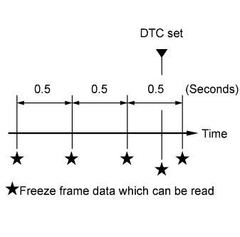
The ECM records engine conditions in the form of freeze frame data every 0.5 seconds. Using the intelligent tester, five separate sets of freeze frame data, including the data values at the time when the DTC was set, can be checked.
-
3 data sets before the DTC was set.
-
1 data set when the DTC was set.
-
1 data set after the DTC was set.
-
These data sets can be used to simulate the condition of the vehicle around the time of the occurrence the malfunction. The data may assist in identifying the cause of the malfunction, and judging whether it was temporary or not.
-
-
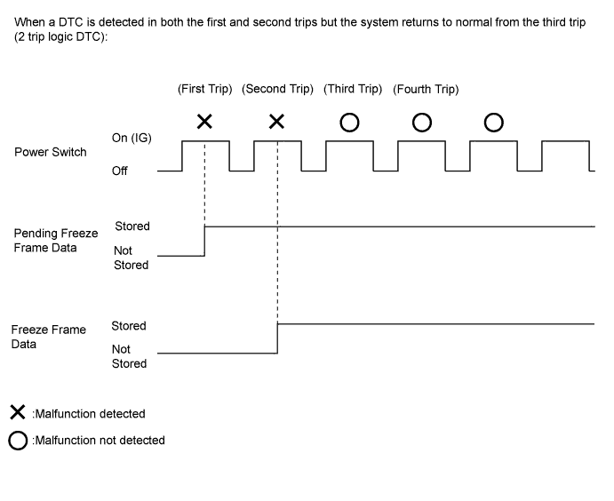
PENDING FREEZE FRAME DATA
Tech Tips
Pending freeze frame data is stored when a 2 trip DTC is first detected during the first trip.
-
Connect the intelligent tester to the DLC3.
-
Turn the power switch on (IG).
-
Turn the tester on.
-
Enter the following menus: Powertrain / Engine and ECT / DTC.
-
Select a DTC in order to display its pending freeze frame data.
Tech Tips
-
Pending freeze frame data is cleared when any of the following occurs.
-
Using the intelligent tester, the DTCs cleared.
-
The cable is disconnected from the negative (-) battery terminal.
-
40 trips with the engine fully warmed up have been performed after returning to normal. (Pending freeze frame data will not be cleared by only returning the system to normal.)
-
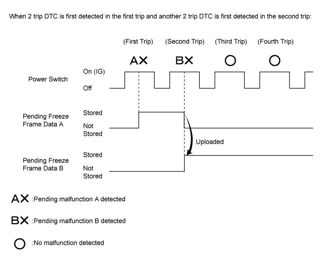
With previous pending freeze frame data stored, if pending freeze frame data is newly stored when a 2 trip DTC is detected in the first trip, the old freeze frame data will be replaced with the new one of the newly detected DTC in the next trip.
-
-
-
LIST OF FREEZE FRAME DATA
Tester Display Measurement Item Diagnostic Note Vehicle Speed Vehicle speed Speed indicated on speedometer Engine Speed Engine speed - Calculate Load Calculated load by ECM - Vehicle Load Vehicle load Load percentage in terms of maximum intake air flow amount MAF Air flow rate from mass air flow meter sub-assembly If value approximately 0.0 gm/sec:
-
Mass air flow meter sub-assembly power source circuit open
-
VG circuit open or short
If value 271.0 gm/sec or more:
-
E2G circuit open
Atmosphere Pressure Atmosphere pressure - MAP Intake manifold pressure - Coolant Temp Engine coolant temperature
-
If value -40°C (-40°F): sensor circuit open
-
If value 140°C (284°F): sensor circuit shorted
Intake Air Intake air temperature
-
If value -40°C (-40°F): sensor circuit open
-
If value 140°C (284°F): sensor circuit shorted
Engine Run Time Engine run time - Initial Engine Coolant Temp Initial engine coolant temperature - Initial Intake Air Temp Initial intake air temperature - Battery Voltage Battery voltage - Throttle Sensor Volt % Throttle sensor positioning Recognition value for throttle opening angle on ECM Throttl Sensor #2 Volt % Absolute throttle sensor positioning #2 Recognition value for throttle opening angle on ECM Throttle Sensor Position Throttle sensor positioning Recognition value for throttle opening angle on ECM Throttle Motor DUTY Throttle actuator - Throttle Position Throttle valve opening angle - ISC Flow Flow rate calculated using information from mass air flow meter sub-assembly - ISC Position Requested throttle opening amount calculated using ISC control - ISC Feedback Value ISC feedback amount - ISC Learning Value ISC learned airflow value - Electric Load Feedback Val Compensation flow rate according to electrical load - Air Conditioner FB Val Compensation flow rate according to air conditioner load - Low Revolution Control Low engine speed control operation state - Deposit Loss Flow Flow loss due to deposits - Injector (Port) Injection period of No. 1 cylinder - Injection Volum (Cylinder1) Injection volume (Cylinder 1) Quantity of fuel injection volume for 10 times Fuel Pump/Speed Status Fuel pump/status - EVAP (Purge) VSV Purge VSV control duty Order signal from ECM Evap Purge Flow Ratio of evaporative purge flow to intake air volume - Purge Density Learn Value Learning value of purge density - EVAP Purge VSV VSV status for EVAP control - Purge Cut VSV Duty Purge VSV duty - Target Air-Fuel Ratio Ratio compared to stoichiometric level - AF Lambda B1S1 Short-term fuel trim associated with bank 1 sensor 1 - AFS Voltage B1S1 Air fuel ratio sensor output voltage for bank 1 sensor 1 - AFS Current B1S1 Air fuel ratio sensor output current for bank 1 sensor 1 Value becomes higher when fuel-cut executed under high engine speed A/F Heater Duty #1 Air fuel ratio sensor heater duty ratio for bank 1 - O2S B1S2 Heated oxygen sensor output voltage for bank 1 sensor 2 - O2 Heater B1S2 Heated oxygen sensor operation - O2 Heater Curr Val B1S2 Heated oxygen sensor current - Short FT #1 Short-term fuel trim of bank 1 Short-term fuel compensation used to maintain air fuel ratio at stoichiometric air fuel ratio Long FT #1 Long-term fuel trim of bank 1 Overall fuel compensation carried out in long-term to compensate continual deviation of short-term fuel trim from central value Total FT #1 Total fuel trim - Fuel System Status #1 Fuel system status (bank 1)
-
OL (Open Loop): Has not yet satisfied conditions to go closed loop
-
CL (Closed Loop): Using air fuel ratio sensor as feedback for fuel control
-
OLDrive: Open loop due to driving conditions (fuel enrichment)
-
OLFault: Open loop due to detected system fault
-
CLFault: Closed loop but air fuel ratio sensor, which is used for fuel control, malfunctioning
Fuel System Status #2 Fuel system status (bank 2) (Unused) - IGN Advance Ignition timing advance for cylinder 1 - Knock Feedback Value Feedback value of knocking - Knock Correct Learn Value Correction learning value of knocking - Idle Spark Advn Ctrl #1 Individual cylinder timing advance compensation amount - Idle Spark Advn Ctrl #2 Individual cylinder timing advance compensation amount - Idle Spark Advn Ctrl #3 Individual cylinder timing advance compensation amount - Idle Spark Advn Ctrl #4 Individual cylinder timing advance compensation amount - Target EGR Position Target EGR position - EGR Step Position Target EGR position - Actual VVT Angle #1 Actual VVT Angle (bank 1) - VVT Control Status #1 VVT control (bank 1) status - Catalyst Temp B1S1 Catalyst temperature (associated sensor 1) - Catalyst Temp B1S2 Catalyst temperature (associated sensor 2) - Closed Throttle Position SW Closed throttle position switch - Fuel Cut Condition Fuel cut condition ON or OFF - TC Terminal TC terminal status - Time after DTC Cleared Time after DTCs cleared - Distance from DTC Cleared Distance traveled after DTCs cleared - Warmup Cycle Cleared DTC Warm-up cycles after DTCs cleared Number of warm-up cycles after DTCs cleared Dist Batt Cable Disconnect Accumulated distance from battery cable disconnected - IG OFF Elapsed Time Cumulative time after power switch off - TC and TE1 TC and CG (TE1) terminals of DLC3 - Ignition Trig. Count Ignition counter to calculated misfire count - Cylinder #1 Misfire Count Misfire count for cylinder 1 - Cylinder #2 Misfire Count Misfire count for cylinder 2 - Cylinder #3 Misfire Count Misfire count for cylinder 3 - Cylinder #4 Misfire Count Misfire count for cylinder 4 - All Cylinders Misfire Count All cylinders misfire count - Misfire RPM Average engine speed when misfire occurs - Misfire Load Average engine load when misfire occurred - Misfire Margin Misfire monitoring - A/F Learn Value Idle #1 Idle area of air fuel ratio learn value - A/F Learn Value Low #1 Low load area of air fuel ratio learn value - A/F Learn Value Mid1 #1 Middle 1 load area of air fuel ratio learn value - A/F Learn Value Mid2 #1 Middle 2 load area of air fuel ratio learn value - A/F Learn Value High #1 High load area of air fuel ratio learn value - Engine Speed (Starter Off) Engine speed after starting the engine - Starter Count Number of times engine cranked after power switch turned on (READY) - Run Dist of Previous Trip Distance driven during previous trip - Engine Starting Time Time elapsed before engine starts - Previous Trip Coolant Temp Engine coolant temperature during previous trip - Previous Trip Intake Temp Intake air temperature during previous trip - Engine Oil Temperature Engine oil temperature (estimated temperature) - Previous Trip Eng Oil Temp Engine oil temperature during previous trip - Ambient Temp for A/C Ambient temperature for A/C - Previous Trip Ambient Temp Ambient temperature during previous trip - Engine Start Hesitation History of hesitation during engine start - Low Rev for Eng Start History of low engine speed after engine start - Minimum Engine Speed Minimum engine speed - Electric Fan Motor Electric cooling fan motor - Idle Fuel Cut Fuel cut idle Idle Fuel Cut = "ON" when the throttle valve is fully closed and the engine speed is high. FC TAU FC TAU This is the fuel cut performed under a very light load to prevent the engine combustion from becoming incomplete. Communication with HV Status of the communication with power management control ECU - Communication with Brake Status of the communication with skid control ECU - Comm with Air Conditioner Status of the communication with air conditioning amplifier assembly - Sports Mode Switch Pattern select switch - Requested Engine Torque Requested engine torque Flag information for hybrid vehicle HV Target Engine Speed HV target engine speed Flag information for hybrid vehicle Actual Engine Torque Actual engine torque Flag information for hybrid vehicle Engine Run Time Engine run time Flag information for hybrid vehicle Request Engine Run Time Request engine run time Flag information for hybrid vehicle Judge Time Engine Ignition Judgment time engine ignition Flag information for hybrid vehicle Judge Time Engine Output Judgment time for time until engine output Flag information for hybrid vehicle Fuel Level Fuel level Flag information for hybrid vehicle ISC Learning Idle speed control learning Flag information for hybrid vehicle F/C for Engine Stop Req Fuel cut for engine stop request Flag information for hybrid vehicle Engine Independent Engine independent operation Flag information for hybrid vehicle Racing Operation Racing operation Flag information for hybrid vehicle Request Warm-up Request engine warm up Flag information for hybrid vehicle Engine Independent Control Engine independent control operation Flag information for hybrid vehicle Elec Water Pump Target Spd Engine water pump assembly target speed - Elec Water Pump Spd Engine water pump assembly speed - ISC Learning Value Idle speed control leaning value Flag information for hybrid vehicle -