SFI SYSTEM (w/ EGR System), Diagnostic DTC:P0031, P0032, P101D

| DTC Code | DTC Name |
|---|---|
| P0031 | Oxygen (A/F) Sensor Heater Control Circuit Low (Bank 1 Sensor 1) |
| P0032 | Oxygen (A/F) Sensor Heater Control Circuit High (Bank 1 Sensor 1) |
| P101D | A/F Sensor Heater Circuit Performance Bank 1 Sensor 1 Stuck ON |
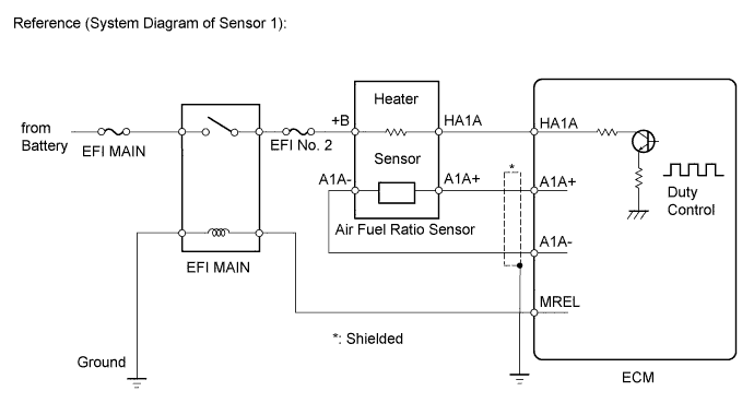
DESCRIPTION
Refer to DTC P2195 Click here.
Tech Tips
-
When either of these DTCs is set, the ECM enters fail-safe mode. The ECM turns off the air fuel ratio sensor heater in fail-safe mode. Fail-safe mode continues until the power switch is turned off.
-
Although the DTC titles say the oxygen sensor, these DTCs relate to the air fuel ratio sensor.
-
Sensor 1 refers to the sensor mounted in front of the Three-way catalytic converter and located near the engine assembly.
-
The ECM uses pulse width modulation to adjust the current through the heater. The air fuel ratio sensor heater circuit uses a relay on the +B side of the circuit.
| DTC No. | DTC Detection Condition | Trouble Area |
|---|---|---|
| P0031 | The heater current is less than the specified value while the heater is operating (1 trip detection logic). (1 trip detection logic) |
|
| P0032 | An air fuel ratio sensor heater current failure (1 trip detection logic). |
|
| P101D | The heater current is higher than the specified value while the heater is not operating (1 trip detection logic). | ECM |
Tech Tips
-
Sensor 1 refers to the sensor closest to the engine assembly.
-
Sensor 2 refers to the sensor farthest away from the engine assembly.
WIRING DIAGRAM
Refer to DTC P2195 Click here.
INSPECTION PROCEDURE
Note
Inspect the fuses for circuits related to this system before performing the following inspection procedure.
Tech Tips
Read freeze frame data using the intelligent tester. The ECM records vehicle and driving condition information as freeze frame data the moment a DTC is stored. When troubleshooting, freeze frame data can be helpful in determining whether the vehicle was running or stopped, whether the engine was warmed up or not, whether the air fuel ratio was lean or rich, as well as other data recorded at the time of a malfunction.
PROCEDURE
-
INSPECT AIR FUEL RATIO SENSOR NO.2 (HEATER RESISTANCE)
-
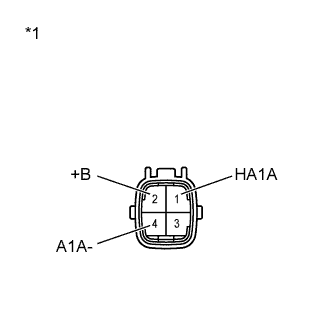
Text in Illustration *1 Component without harness connected
(to Air Fuel Ratio Sensor)
Disconnect the air fuel ratio sensor connector.
-
Measure the resistance according to the value(s) in the table below.
Standard Resistance Tester Connection Condition Specified Condition 1 (HA1A) - 2 (+B) 20°C (68°F) 1.8 to 3.4 Ω 1 (HA1A) - 4 (A1A-) Always 10 kΩ or higher -
Reconnect the air fuel ratio sensor connector.
NG 
REPLACE AIR FUEL RATIO SENSOR NO.2 Click here
OK 
-
-
CHECK TERMINAL VOLTAGE (POWER SOURCE)
-
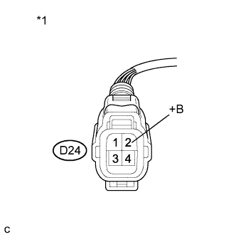
Text in Illustration *1 Front view of wire harness connector
(to Air Fuel Ratio Sensor)
Disconnect the air fuel ratio sensor connector.
-
Turn the power switch on (IG).
-
Measure the voltage according to the value(s) in the table below.
Standard Voltage Tester Connection Switch Condition Specified Condition D24-2 (+B) - Body ground Power switch on (IG) 11 to 14 V -
Reconnect the air fuel ratio sensor connector.
NG
REPAIR OR REPLACE HARNESS OR CONNECTOR (AIR FUEL RATIO SENSOR - EFI MAIN RELAY)
OK
-
-
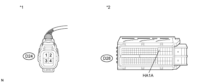
CHECK HARNESS AND CONNECTOR (AIR FUEL RATIO SENSOR - ECM)
-
Disconnect the air fuel ratio sensor connector.
-
Disconnect the ECM connector.
-
Measure the resistance according to the value(s) in the table below.
Standard Resistance (Check for Open) Tester Connection Condition Specified Condition D24-1 (HA1A) - D28-18 (HA1A) Always Below 1 Ω Standard Resistance (Check for Short) Tester Connection Condition Specified Condition D24-1 (HA1A) or D28-18 (HA1A) - Body ground Always 10 kΩ or higher Text in Illustration *1 Front view of wire harness connector
(to Air Fuel Ratio Sensor)
*2 Front view of wire harness connector
(to ECM)
-
Reconnect the air fuel ratio sensor connector.
-
Reconnect the ECM connector.
NG
REPAIR OR REPLACE HARNESS OR CONNECTOR (AIR FUEL RATIO SENSOR - ECM)
OK
-
-
CHECK WHETHER DTC OUTPUT RECURS (DTC P0031, P0032 OR P101D)
-
Connect the intelligent tester to the DLC3.
-
Turn the power switch on (IG).
-
Turn the tester on.
-
Clear the DTCs Click here.
-
Put the engine in inspection mode Click here.
-
Start the engine and idle it for 5 minutes or more.
-
With the vehicle stationary, depress the accelerator pedal and maintain an engine speed for 2500 rpm for 1 minute.
-
Idle the engine for 5 minutes or more.
-
Enter the following menus: Powertrain / Engine and ECT / DTC.
-
Read the DTCs.
Result Result Proceed to DTC is not output A DTC P0031, P0032 or P101D is output B
B
REPLACE ECM Click here
A 
CHECK FOR INTERMITTENT PROBLEMS Click here
-