NAVIGATION SYSTEM (for DVD) TERMINALS OF ECU

-
NAVIGATION RECEIVER ASSEMBLY
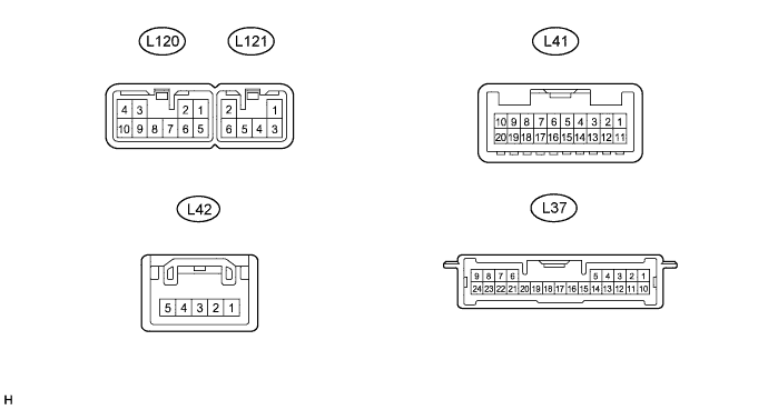
Terminal No. (Symbol) Wiring Color Terminal Description Condition Specified Condition L120-1 (FR+) - L120-7 (GND) LG - BR Sound signal (Front right) Audio system playing A waveform synchronized with sounds is output L120-2 (FL+) - L120-7 (GND) P - BR Sound signal (Front left) Audio system playing A waveform synchronized with sounds is output L120-3 (ACC) - L120-7 (GND) GR - BR Accessory (ON) Power switch on (ACC) 11 to 14 V Power switch off Below 1 V L120-4 (B) - L120-7 (GND) SB - BR Battery Power switch off 11 to 14 V L120-5 (FR-) - L120-7 (GND) L - BR Sound signal (Front right) Audio system playing A waveform synchronized with sounds is output L120-6 (FL-) - L120-7 (GND) V - BR Sound signal (Front left) Audio system playing A waveform synchronized with sounds is output L120-7 (GND) - Body ground BR - Body ground Ground Always Below 1 V L120-8 (ANT) - L120-7 (GND) BE - BR Power source of antenna Power switch on (IG)
Radio switch on and AM or FM
8 V or higher L120-9 (AMP) - L120-7 (GND) W - BR Audio system playing signal Power switch on (IG)
Audio system playing
8 V or higher L120-10 (ILL+) - L120-7 (GND) G - BR Illumination signal Power switch on (IG)
Light control switch off → tail or on
Below 1 V → 11 to 14 V L121-1 (RR+) - L120-7 (GND) R - BR Sound signal (Rear right) Audio system playing A waveform synchronized with sounds is output L121-2 (RL+) - L120-7 (GND) B - BR Sound signal (Rear left) Audio system playing A waveform synchronized with sounds is output L121-3 (RR-) - L120-7 (GND) W - BR Sound signal (Rear right) Audio system playing A waveform synchronized with sounds is output L121-6 (RL-) - L120-7 (GND) Y - BR Sound signal (Rear left) Audio system playing A waveform synchronized with sounds is output L41-6 (SWG) - Body ground P - Body ground Steering pad switch signal Always Below 1 V L41-7 (SW1) - L41-6 (SWG) R - P Steering pad switch signal No switch pushed → MODE switch pushed → ON HOOK switch pushed → OFF HOOK switch pushed → VOICE switch pushed 4.44 to 5.43 V → 0.45 to 0.65 V → 1.19 to 1.49 V → 2.09 to 2.54 V → 3.2 to 3.88 V L41-8 (SW2) - L41-6 (SWG) G - P Steering pad switch signal No switch is pushed → SEEK+ switch pushed → SEEK- switch pushed → VOL+ switch pushed → VOL- switch pushedd 4.44 to 5.43 V → 0.45 to 0.65 V → 1.19 to 1.49 V → 2.09 to 2.54 V → 3.2 to 3.88 V L41-9 (TX1+) LG AVC-LAN communication signal - - L41-10 (TX1-) P AVC-LAN communication signal - - L41-15 (ARI) - L41-16 (ASGN) B - W Sound signal (Right) External device playing (When stereo jack used) A waveform synchronized with sounds is output L41-16 (ASGN) - L120-7 (GND) W - BR Sound signal ground Always Below 1 V L41-17 (ALI) - L41-16 (ASGN) R - W Sound signal (Left) External device playing (When stereo jack used) A waveform synchronized with sounds is output L41-18 (AGND) - Body ground Shield - Body ground Shield ground Always Below 1 V L41-19 (AUXI) - L120-7 (GND) W - BR External device connection detection signal External device connected Below 1 V External device not connected 2.1 to 3 V L42-1 (PKB) - L120-7 (GND) R - BR Parking brake signal See "Vehicle Signal Check Mode" in Operation Check Click here
- L42-2 (IG) - L120-7 (GND) B - BR Power source (IG) Power switch on (IG) 11 to 14 V Power switch off Below 1 V L42-3 (SPD) - L120-7 (GND) V - BR Speed signal from combination meter assembly See "Vehicle Signal Check Mode" in Operation Check Click here
- L42-5 (REV) - L120-7 (GND) P - BR Reverse signal See "Vehicle Signal Check Mode" in Operation Check Click here
- L37-2 (CANH) G CAN communication signal - - L37-3 (CANL) W CAN communication signal - - L37-5 (SNS2) - L120-7 (GND) B - BR Microphone connection detection signal Always Below 0.1 V L37-17 (MACC) - L120-7 (GND) R - BR Telephone microphone assembly power supply Power switch off → on (IG) Below 1 V → 5 V L37-18 (SGND) - L120-7 (GND) Shield - BR Shield ground Always Below 1 V L37-19 (MIN+) - L120-7 (GND) B - BR Microphone voice signal See "Microphone & Voice Recognition Check" in Operation Check Click here
- L37-20 (MIN-) - Body ground W - Body ground Microphone voice signal See "Microphone & Voice Recognition Check" in Operation Check Click here
- -
STEREO COMPONENT AMPLIFIER ASSEMBLY

Terminal No. (Symbol) Wiring Color Terminal Description Condition Specification L108-1 (RL+) - L108-10 (GND) P - BR Sound signal (Front left) Audio system playing A waveform synchronized with sounds is input L108-2 (RR+) - L108-10 (GND) LG - BR Sound signal (Front right) Audio system playing A waveform synchronized with sounds is input L108-3 (WFR+) - L108-10 (GND) LG - BR Sound signal (Front right) Audio system playing A waveform synchronized with sounds is output L108-4 (WFL+) - L108-10 (GND) P - BR Sound signal (Front left) Audio system playing A waveform synchronized with sounds is output L108-5 (+B) - L108-10 (GND) R - BR Battery Power switch off 11 to 14 V L108-6 (RL-) - L108-10 (GND) V - BR Sound signal (Front left) Audio system playing A waveform synchronized with sounds is input L108-7 (RR-) - L108-10 (GND) L - BR Sound signal (Front right) Audio system playing A waveform synchronized with sounds is input L108-8 (WFR-) - L108-10 (GND) L - BR Sound signal (Front right) Audio system playing A waveform synchronized with sounds is output L108-9 (AMP+) - L108-10 (GND) W - BR Audio system playing signal Audio system playing 8 V or higher L108-10 (GND) - Body ground BR - Body ground Ground Always Below 1 V L108-11 (WFL-) - L108-10 (GND) V - BR Sound signal (Front left) Audio system playing A waveform synchronized with sounds is output L108-12 (ACC) - L108-10 (GND) GR - BR Accessory (ON) Power switch on (ACC) 11 to 14 V Power switch off Below 1 V -
PARKING ASSIST ECU Click here