NAVIGATION SYSTEM (for Navigation Receiver Type) Reverse Signal Circuit
DESCRIPTION
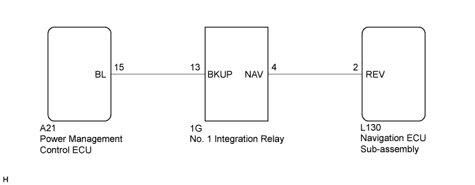
The navigation ECU sub-assembly receives a reverse signal from the power management control ECU via the No. 1 integration relay.
WIRING DIAGRAM
INSPECTION PROCEDURE
PROCEDURE
-
CHECK HARNESS AND CONNECTOR (REVERSE SIGNAL)
-
Disconnect the navigation ECU sub-assembly connector.
-
Measure the voltage according to the value(s) in the table below.
Standard Voltage Tester Connection Condition Specified Condition L130-2 (REV) - Body ground Power switch on (READY)
Reverse (R) selected
11 to 15.5 V L130-2 (REV) - Body ground Power switch on (READY)
Except reverse (R) selected
Below 1 V
NG 
CHECK HARNESS AND CONNECTOR (NAVIGATION ECU SUB-ASSEMBLY - NO. 1 INTEGRATION RELAY) Click here
OK 
PROCEED TO NEXT SUSPECTED AREA SHOWN IN PROBLEM SYMPTOMS TABLE Click here
-
-
CHECK HARNESS AND CONNECTOR (NAVIGATION ECU SUB-ASSEMBLY - NO. 1 INTEGRATION RELAY)
-
Disconnect the navigation ECU sub-assembly connector.
-
Disconnect the No. 1 integration relay connector.
-
Measure the resistance according to the value(s) in the table below.
Standard Resistance Tester Connection Condition Specified Condition L130-2 (REV) - 1G-4 (NAV) Always Below 1 Ω L130-2 (REV) - Body ground Always 10 kΩ or higher
NG 
REPAIR OR REPLACE HARNESS OR CONNECTOR
OK 
-
-
CHECK HARNESS AND CONNECTOR (NO. 1 INTEGRATION RELAY - POWER MANAGEMENT CONTROL ECU)
-
Disconnect the No. 1 integration relay connector.
-
Disconnect the power management control ECU connector.
-
Measure the resistance according to the value(s) in the table below.
Standard Resistance Tester Connection Condition Specified Condition 1G-13 (BKUP) - A21-15 (BL) Always Below 1 Ω 1G-13 (BKUP) - Body ground Always 10 kΩ or higher
NG
REPAIR OR REPLACE HARNESS OR CONNECTOR
OK
-
-
REPLACE NO. 1 INTEGRATION RELAY
-
Replace the No. 1 integration relay with a new one or known good one Click here.
-
Check that the malfunction disappears.
OK Malfunction disappears.
NG
REPLACE POWER MANAGEMENT CONTROL ECU Click here
OK
END (NO. 1 INTEGRATION RELAY WAS DEFECTIVE)
-