NAVIGATION SYSTEM (for Navigation Receiver Type) Radio Broadcast cannot be Received or Poor Reception
INSPECTION PROCEDURE
PROCEDURE
-
CHECK NAVIGATION ECU SUB-ASSEMBLY
-
Check the radio automatic station search function.
-
Check the radio automatic station search function by activating it.
Result Result Proceed to Automatic station search function does not stop A Automatic station search function stops on a station B
-
B 
REPLACE NAVIGATION ECU SUB-ASSEMBLY Click here
A 
-
-
CHECK OPTIONAL COMPONENTS
-
Check if any optional components that may decrease reception capacity, such as sunshade film or a telephone antenna, are installed.
Result Result Proceed to Optional components are not installed A Optional components are installed B Note
Do not remove optional components without the permission of the customer.
B
REMOVE OPTIONAL COMPONENTS AND CHECK AGAIN (SEE NOTICE ABOVE)
A
-
-
CHECK RADIO ANTENNA
-
Preparation for check
-
Remove the roof antenna pole sub-assembly from the amplifier antenna assembly (for Roof).
-
-
Check for noise
-
Turn the power switch on (ACC) with the navigation ECU sub-assembly connector connected.
-
Turn the radio on and tune into AM mode.
-
Place a screwdriver, thin wire, or other metal object on the amplifier antenna threaded installation portion for the roof antenna pole sub-assembly and check that noise can be heard from the speakers.
Result Result Proceed to Noise does not occur A Noise occurs B
-
B
REPLACE NAVIGATION ECU SUB-ASSEMBLY Click here
A
-
-
CHECK NAVIGATION ECU SUB-ASSEMBLY
-
Preparation for check
-
Remove the antenna connector from the navigation ECU sub-assembly.
-
-
Check for noise
-
Turn the power switch on (ACC) with the navigation ECU sub-assembly connector connected.
-
Turn the radio on and tune into AM mode.
-
Place a screwdriver, thin wire or other metal object on the navigation ECU sub-assembly antenna jack and check that noise can be heard from the speakers.
OK Noise can be heard from the speakers.
-
NG
REPLACE NAVIGATION ECU SUB-ASSEMBLY Click here
OK
-
-
INSPECT NAVIGATION ECU SUB-ASSEMBLY
-
Disconnect the navigation ECU sub-assembly connector.
-
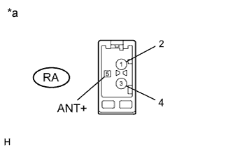
Text in Illustration *a Component without harness connected
(Navigation ECU Sub-assembly)
Measure the voltage according to the value(s) in the table below.
Standard Voltage Tester Connection Condition Specified Condition RA-5 (ANT+) - Body ground Power switch on (ACC)
Radio switch on and AM or FM selected
11 to 14 V
NG
REPLACE NAVIGATION ECU SUB-ASSEMBLY Click here
OK
-
-
REPLACE NO. 2 ANTENNA CORD SUB-ASSEMBLY
-
Replace the No. 2 antenna cord sub-assembly and check if radio broadcasts can be received normally Click here.
OK Radio broadcasts can be received normally.
NG 
INSPECT NO. 4 ANTENNA CORD SUB-ASSEMBLY Click here
OK 
NORMAL OPERATION
-
-
INSPECT NO. 4 ANTENNA CORD SUB-ASSEMBLY
-
Disconnect the No. 4 antenna cord sub-assembly.
-
Measure the resistance of the No. 4 antenna cord sub-assembly to check for an open circuit in the No. 4 antenna cord sub-assembly.
Standard Resistance Below 1 Ω -
Measure the resistance between the No. 4 antenna cord sub-assembly and body ground to check for a short circuit in the No. 4 antenna cord sub-assembly.
Standard Resistance 10 kΩ or higher
NG
REPLACE NO. 4 ANTENNA CORD SUB-ASSEMBLY Click here
OK
-
-
INSPECT NO. 5 ANTENNA CORD SUB-ASSEMBLY
-
Disconnect the No. 5 antenna cord sub-assembly.
-
Measure the resistance of the No. 5 antenna cord sub-assembly to check for an open circuit in the No. 5 antenna cord sub-assembly.
Standard Resistance Below 1 Ω -
Measure the resistance between the No. 5 antenna cord sub-assembly and body ground to check for a short circuit in the No. 5 antenna cord sub-assembly.
Standard Resistance 10 kΩ or higher
NG
REPLACE NO. 5 ANTENNA CORD SUB-ASSEMBLY Click here
OK
-
-
CHECK ROOF ANTENNA POLE SUB-ASSEMBLY
-
Check that the roof antenna pole sub-assembly is securely installed Click here.
OK The roof antenna pole sub-assembly is installed properly.
NG
CHECK AND REPLACE ROOF ANTENNA POLE SUB-ASSEMBLY Click here
OK
-
-
REPLACE AMPLIFIER ANTENNA ASSEMBLY (for Roof)
-
Replace the amplifier antenna assembly (for Roof) and check if radio broadcasts can be received normally Click here.
OK Radio broadcasts can be received normally.
NG
REPLACE NAVIGATION ECU SUB-ASSEMBLY Click here
OK
NORMAL OPERATION
-