NAVIGATION SYSTEM (for Radio and Display Type) Display Signal Circuit between Radio Receiver and Extension Module
DESCRIPTION
This circuit sends a display signal from the extension module to the radio and display receiver assembly.
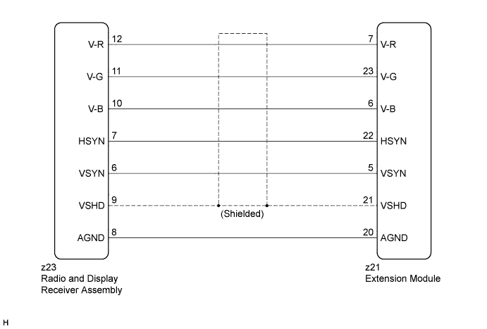
WIRING DIAGRAM
INSPECTION PROCEDURE
PROCEDURE
-
CHECK HARNESS AND CONNECTOR (RADIO AND DISPLAY RECEIVER ASSEMBLY - EXTENSION MODULE)
-
Disconnect the radio and display receiver assembly connector.
-
Disconnect the extension module connector.
-
Measure the resistance according to the value(s) in the table below.
Standard Resistance Tester Connection Condition Specified Condition z23-12 (V-R) - z21-7 (V-R) Always Below 1 Ω z23-11 (V-G) - z21-23 (V-G) Always Below 1 Ω z23-10 (V-B) - z21-6 (V-B) Always Below 1 Ω z23-7 (HSYN) - z21-22 (HSYN) Always Below 1 Ω z23-6 (VSYN) - z21-5 (VSYN) Always Below 1 Ω z23-9 (VSHD) - z21-21 (VSHD) Always Below 1 Ω z23-8 (AGND) - z21-20 (AGND) Always Below 1 Ω z23-12 (V-R) - Body ground Always 10 kΩ or higher z23-11 (V-G) - Body ground Always 10 kΩ or higher z23-10 (V-B) - Body ground Always 10 kΩ or higher z23-7 (HSYN) - Body ground Always 10 kΩ or higher z23-6 (VSYN) - Body ground Always 10 kΩ or higher z23-9 (VSHD) - Body ground Always 10 kΩ or higher z23-8 (AGND) - Body ground Always 10 kΩ or higher
NG 
REPAIR OR REPLACE HARNESS OR CONNECTOR
OK 
PROCEED TO NEXT SUSPECTED AREA SHOWN IN PROBLEM SYMPTOMS TABLE Click here
-