RADIO ANTENNA CORD INSTALLATION

-
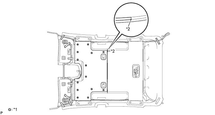
INSTALL NO. 5 ANTENNA CORD SUB-ASSEMBLY
-
Engage the 4 clamps.
-
Install the No. 5 antenna cord sub-assembly with the bolt.
-
Connect the connector.
-
-
INSTALL NO. 4 ANTENNA CORD SUB-ASSEMBLY
Tech Tips
Double-sided tape and tape are not available as supply parts. If the tape still has enough adhesion to secure the roof headlining and antenna cord, reuse it. If the roof headlining has been replaced with a new one, or if the tape and/or the double-sided tape is no longer sticky, apply new tape following the procedure below.
If the double-sided tape cannot be reused:
-
Peel off the release paper from one side of new double-sided tape and apply the new double-sided tape to the position indicated in the illustration. Be careful not to touch the adhesive surface.
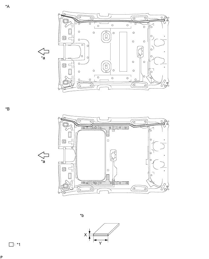
Text in Illustration *A w/o Sliding Roof *B w/ Sliding Roof *1 Double-sided Tape - - *a Front *b Double-sided Tape Size Double-sided Tape Size Area Dimension X 1.0 mm (0.0394 in.) Y 10.0 mm (0.394 in.) Note
Be sure to apply the double-sided tape carefully so that the tape will not be misaligned or come off.
-
Peel off the release paper from the double-sided tape. Be careful not to touch the adhesive surface.
-
Align the vehicle front side marking (pink) on the No. 4 antenna cord sub-assembly with the vehicle front side tab on the roof headlining, and wrap the tape over the antenna cord to install it. (1)
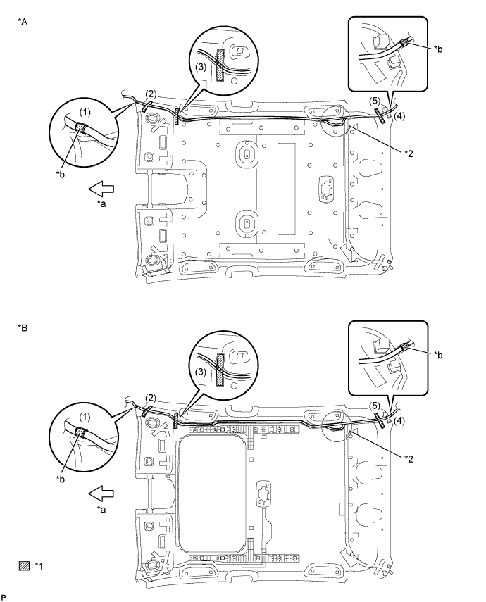
Text in Illustration *A w/o Sliding Roof *B w/ Sliding Roof *1 Tape *2 Extra Cord Storage Area *a Front *b Pink Tech Tips
If the tape cannot be reused, packing tape can be used as a substitute.
-
Temporarily install the front side of the No. 4 antenna cord sub-assembly with the adhesive tape. (2)
-
Temporarily install the front side of the No. 4 antenna cord sub-assembly with the adhesive tape. (3)
-
Temporarily install the No. 4 antenna cord sub-assembly by placing it on the double-sided tape from the front of the vehicle to the point just before the extra cord storage area.
-
Align the vehicle rear marking (pink) on the No. 4 antenna cord sub-assembly with the tape attachment location (scribe line) of the roof headlining, and wrap the tape over the antenna cord to install it. (4)
Tech Tips
If the tape cannot be reused, packing tape can be used as a substitute.
-
Temporarily install the rear side of the No. 4 antenna cord sub-assembly with the adhesive tape. (5)
-
Temporarily install the No. 4 antenna cord sub-assembly by placing it on the double-sided tape from the rear of the vehicle to the point just before the extra cord storage area.
-
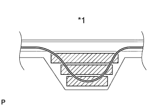
Text in Illustration *1 Extra Cord Storage Area Using double-sided tape, place any excess No. 4 antenna cord sub-assembly in the extra cord storage area to finish installing the antenna cord.
Tech Tips
Attach 3 pieces of double-sided tape to the extra cord storage area as shown in the illustration.
-
-
INSTALL NO. 3 ROOF SILENCER PAD (w/o Sliding Roof)
-
Align the markings on the roof headlining assembly with the No. 3 roof silencer pad and install the set plate using hot-melt glue as shown in the illustration.
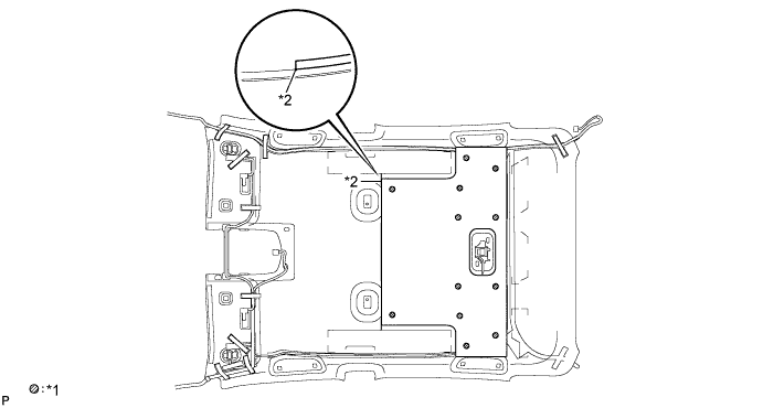
Text in Illustration *1 Hot-melt Glue *2 Marking Note
Securely attach the No. 1 roof wire. Failure to do so may cause abnormal noise.
-
-
INSTALL NO. 2 ROOF SILENCER PAD (w/o Sliding Roof)
-
Align the markings on the roof headlining assembly with the No. 2 roof silencer pad and install the set plate using hot-melt glue as shown in the illustration.
Text in Illustration *1 Hot-melt Glue *2 Marking
-
-
INSTALL ROOF HEADLINING ASSEMBLY
-
INSTALL NO. 2 ANTENNA CORD SUB-ASSEMBLY (for LHD)
-
for Plug Type Antenna Cord:
-
Engage the 4 clamps.
-
Install the No. 2 antenna cord sub-assembly with the bolt.
-
Connect the 2 connectors.
-
-
for Connector Type Antenna Cord:
-
Engage the 4 clamps.
-
Install the No. 2 antenna cord sub-assembly with the bolt.
-
Connect the connector.
-
-
w/ Digital Audio Broadcasting Antenna:
-
Engage the 5 clamps.
-
Install the No. 2 antenna cord sub-assembly with the bolt.
-
Connect the 2 connectors.
-
-
-
INSTALL NO. 2 ANTENNA CORD SUB-ASSEMBLY (for RHD)
-
Plug Type Antenna Cord:
-
Engage the 5 clamps.
-
Install the No. 2 antenna cord sub-assembly with the bolt.
-
Connect the 2 connectors.
-
-
for Connector Type Antenna Cord:
-
Engage the 5 clamps.
-
Install the No. 2 antenna cord sub-assembly with the bolt.
-
Connect the connector.
-
-
w/ Digital Audio Broadcasting Antenna:
-
Engage the 6 clamps.
-
Install the No. 2 antenna cord sub-assembly with the bolt.
-
Connect the 2 connectors.
-
-
-
INSTALL UPPER INSTRUMENT PANEL ASSEMBLY