AUDIO AND VISUAL SYSTEM Radio Broadcast cannot be Received or Poor Reception
INSPECTION PROCEDURE
PROCEDURE
-
CHECK RADIO RECEIVER ASSEMBLY
-
Check the radio automatic station search function.
-
Check the radio automatic station search function by activating it.
Result Result Proceed to Automatic station search function stops on a station A Automatic station search function does not stop B
-
B 
CHECK OPTIONAL COMPONENTS Click here
A 
REPLACE RADIO RECEIVER ASSEMBLY Click here
-
-
CHECK OPTIONAL COMPONENTS
-
Check optional components (sunshade film, telephone antenna, etc.).
-
Check if any optional components that may decrease reception capacity, such as sunshade film or a telephone antenna, are installed.
Result Result Proceed to Optional components are installed A Optional components are not installed B Note
Do not remove any optional components installed by the customer without his or her consent.
-
B
CHECK RADIO ANTENNA Click here
A
REMOVE OPTIONAL COMPONENTS AND CHECK AGAIN (SEE NOTICE ABOVE)
-
-
CHECK RADIO ANTENNA
-
Preparation for check
-
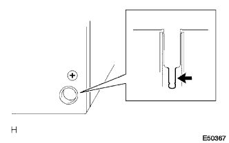
Remove the roof antenna pole sub-assembly from the amplifier antenna assembly.
-
-
Check for noise
-
Turn the power switch on (ACC) with the radio receiver assembly connector connected.
-
Turn the radio on and tune into AM mode.
-
Place a screwdriver, thin wire, or other metal object on the amplifier antenna threaded installation portion for the roof antenna pole sub-assembly and check that noise can be heard from the speakers.
Result Result Proceed to Noise does not occur A Noise occurs B
-
B 
REPLACE RADIO RECEIVER ASSEMBLY Click here
A 
-
-
CONFIRM MODEL
-
Check the type of connection between the antenna cord and radio receiver assembly.
Result Result Proceed to for Plug Type Antenna Cord A for Connector Type Antenna Cord B
B
CHECK RADIO RECEIVER ASSEMBLY Click here
A
-
-
CHECK RADIO RECEIVER ASSEMBLY
-
Preparation for check
-
Remove the antenna plug from the radio receiver assembly.
-
-
Check for noise
-
Turn the power switch on (ACC) with the radio receiver assembly connector connected.
-
Turn the radio on and tune into AM mode.
-
Place a screwdriver, thin wire or other metal object on the radio receiver assembly antenna jack and check that noise can be heard from the speakers.
OK Noise can be heard from the speaker.
-
NG
REPLACE RADIO RECEIVER ASSEMBLY Click here
OK
-
-
CHECK HARNESS AND CONNECTOR (RADIO RECEIVER ASSEMBLY - AMPLIFIER ANTENNA ASSEMBLY)
-
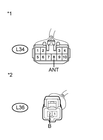
Text in Illustration *1 Front view of wire harness connector
(to Radio Receiver Assembly)
*2 Front view of wire harness connector
(to Amplifier Antenna Assembly)
Disconnect the radio receiver assembly and amplifier antenna assembly connectors.
-
Measure the resistance according to the value(s) in the table below.
Standard Resistance Tester Connection Condition Specified Condition L34-8 (ANT) - L36-2 (B) Always Below 1 Ω L34-8 (ANT) - Body ground Always 10 kΩ or higher
NG
REPAIR OR REPLACE HARNESS OR CONNECTOR
OK
-
-
INSPECT RADIO RECEIVER ASSEMBLY
-
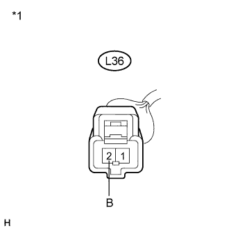
Text in Illustration *1 Front view of wire harness connector
(to Amplifier Antenna Assembly)
Reconnect the radio receiver assembly connector.
-
Measure the voltage according to the value(s) in the table below.
Standard Voltage Tester Connection Condition Specified Condition L36-2 (B) - Body ground Power switch on (IG)
Radio switch on
8 V or higher
NG
REPLACE RADIO RECEIVER ASSEMBLY Click here
OK
-
-
CHECK ANTENNA CORD
-
Remove the antenna plug of the radio receiver assembly and antenna.
-
Measure the resistance between the antenna and radio receiver assembly to check for an open circuit in the antenna cord.
Standard Resistance Below 1 Ω -
Measure the resistance between the antenna cord and body ground to check for a short circuit in the antenna cord.
Standard Resistance 10 kΩ or higher Proceed to the next step based on the inspection result.
Result Result Proceed to NG A OK B
B
REPLACE AMPLIFIER ANTENNA ASSEMBLY Click here
A
REPLACE ANTENNA CORD Click here
-
-
CHECK RADIO RECEIVER ASSEMBLY
-
Preparation for check
-
Remove the antenna connector from the radio receiver assembly.
-
-
Check for noise
-
Turn the power switch on (ACC) with the radio receiver assembly connector connected.
-
Turn the radio on and tune into AM mode.
-
Place a screwdriver, thin wire or other metal object on the radio receiver assembly antenna jack and check that noise can be heard from the speakers.
OK Noise can be heard from the speaker.
-
NG
REPLACE RADIO RECEIVER ASSEMBLY Click here
OK
-
-
INSPECT RADIO RECEIVER ASSEMBLY
-
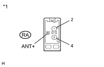
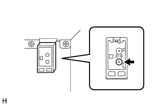
Text in Illustration *1 Component without harness connected
(Radio Receiver Assembly)
Disconnect the radio receiver assembly connector.
-
Measure the voltage according to the value(s) in the table below.
Standard Voltage Tester Connection Condition Specified Condition RA-5 (ANT+) - Body ground Power switch on (ACC)
Radio switch on
8 V or higher
NG
REPLACE RADIO RECEIVER ASSEMBLY Click here
OK
-
-
CHECK ANTENNA CORD
-
Remove the antenna connector of the radio receiver assembly and antenna.
-
Measure the resistance between the antenna and radio receiver assembly to check for an open circuit in the antenna cord.
Standard Resistance Below 1 Ω -
Measure the resistance between the antenna cord and body ground to check for a short circuit in the antenna cord.
Standard Resistance 10 kΩ or higher
NG
REPLACE ANTENNA CORD Click here
OK
-
-
REPLACE AMPLIFIER ANTENNA ASSEMBLY
-
Replace the amplifier antenna assembly and check if radio broadcasts can be received normally Click here.
OK Radio broadcasts can be received.
NG
REPLACE RADIO RECEIVER ASSEMBLY Click here
OK
NORMAL OPERATION
-