STEERING PAD SWITCH INSPECTION

-
INSPECT STEERING PAD SWITCH ASSEMBLY (Before October, 2010)
-
Measure the resistance according to the value(s) in the table below.
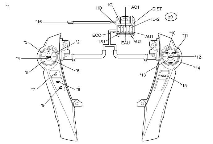
Standard Resistance Tester Connection Switch Condition Specified Condition z9-1 (HO) - Terminal A Always Below 1 Ω z9-3 (AC1) - z9-8 (EAU) No switch pushed 95 to 105 kΩ z9-3 (AC1) - z9-8 (EAU) R/F switch: ON 323 to 335 Ω z9-3 (AC1) - z9-8 (EAU) TEMP+ switch: pushed 980 to 1020 Ω z9-3 (AC1) - z9-8 (EAU) TEMP- switch: pushed 3048 to 3172 Ω z9-4 (DIST) - z9-6 (ECC) Distance control switch: ON Below 2.5 Ω z9-4 (DIST) - z9-6 (ECC) No switch pushed 1 MΩ or higher z9-9 (AU2) - z9-8 (EAU) No switch pushed 95 to 105 kΩ z9-9 (AU2) - z9-8 (EAU) MODE switch: pushed Below 2.5 Ω z9-9 (AU2) - z9-8 (EAU) Voice switch: pushed 3048 to 3172 Ω z9-9 (AU2) - z9-8 (EAU) On Hook switch: pushed 323 to 335 Ω z9-9 (AU2) - z9-8 (EAU) Off Hook switch: pushed 980 to 1020 Ω z9-10 (AU1) - z9-8 (EAU) No switch pushed 95 to 105 kΩ z9-10 (AU1) - z9-8 (EAU) Seek+ switch: pushed Below 2.5 Ω z9-10 (AU1) - z9-8 (EAU) Seek- switch: pushed 323 to 335 Ω z9-10 (AU1) - z9-8 (EAU) Volume+ switch: pushed 980 to 1020 Ω z9-10 (AU1) - z9-8 (EAU) Volume- switch: pushed 3048 to 3172 Ω Tech Tips
If the result is not as specified, replace the steering pad switch assembly.
Text in Illustration *1 Component without harness connected
(Steering Pad Switch Assembly)
*2 Volume+ *3 Volume- *4 MODE *5 Seek- *6 Seek+ *7 Voice switch *8 On Hook *9 Off Hook *10 TRIP switch *11 DISP switch *12 R/F switch *13 TEMP- *14 TEMP+ *15 Distance control switch *16 Terminal-A -
Check the illumination
-
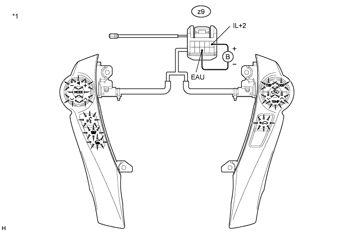
Connect a positive (+) lead to terminal IL+2 and a negative (-) lead to terminal EAU of the steering pad switch assembly connector.
-
Check that the switch illumination comes on.
OK Steering pad switch illumination comes on. Tech Tips
If the result is not as specified, replace the steering pad switch assembly.
Text in Illustration *1 Component without harness connected
(Steering Pad Switch Assembly)
-
-
-
INSPECT STEERING PAD SWITCH LH (From October, 2010)
-
Measure the resistance according to the value(s) in the table below.
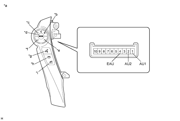
Standard Resistance Tester Connection Condition Specified Condition 1 (AU1) - 4 (EAU) No switch pushed 95 to 105 kΩ Seek+ switch pushed Below 2.5 Ω Seek- switch pushed 323 to 335 Ω Volume+ switch pushed 980 to 1020 Ω Volume- switch pushed 3048 to 3172 Ω 2 (AU2) - 4 EAU) No switch pushed 95 to 105 kΩ MODE switch pushed Below 2.5 Ω On hook switch pushed 323 to 335 Ω Off hook switch pushed 980 to 1020 Ω Voice switch pushed 3048 to 3172 Ω Tech Tips
If the result is not as specified, replace the steering pad switch LH.
Text in Illustration *a Component without harness connected
(Steering Pad Switch LH)
*b Volume+ *c Volume- *d MODE *e Seek+ *f Seek- *g Voice *h On hook *i Off hook - - -
Check the illumination.
-
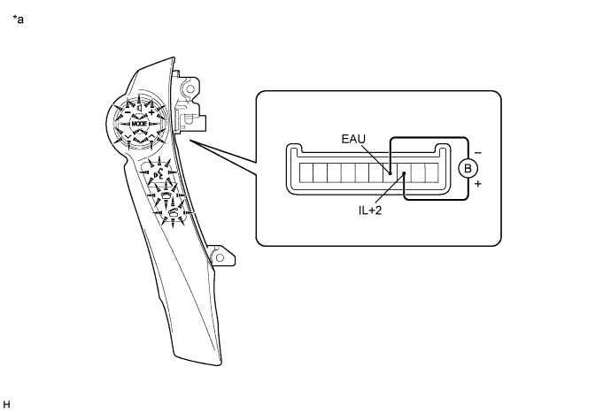
Connect a battery positive (+) lead to terminal IL+2 and a negative (-) lead to terminal EAU of the steering pad switch LH connector.
-
Check that the switch illumination comes on.
OK Steering pad switch illumination comes on. Tech Tips
If the result is not as specified, replace the steering pad switch LH.
Text in Illustration *a Component without harness connected
(Steering Pad Switch LH)
- -
-
-
-
INSPECT STEERING PAD SWITCH RH (From October, 2010)
-
Measure the resistance according to the value(s) in the table below.
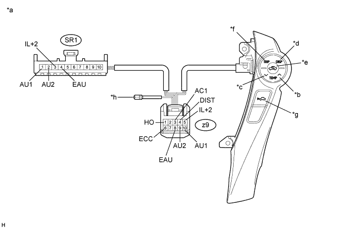
Standard Resistance Tester Connection Condition Specified Condition z9-1 (HO) - Terminal-A Always Below 1 Ω z9-3 (AC1) - z9-8 (EAU) No switch pushed 95 to 105 kΩ R/F switch pushed 323 to 335 Ω TEMP+ switch pushed 980 to 1020 Ω TEMP- switch pushed 3048 to 3172 Ω z9-4 (DIST) - z9-6 (ECC) No switch pushed 1 MΩ or higher Distance control switch pushed Below 2.5 Ω SR1-3 (IL+2) - z9-5 (IL+2) Always Below 1 Ω SR1-1 (AU1) - z9-10 (AU1) Always Below 1 Ω SR1-2 (AU2) - z9-9 (AU2) Always Below 1 Ω SR1-4 (EAU) - z9-8 (EAU) Always Below 1 Ω Tech Tips
If the result is not as specified, replace the steering pad switch RH.
Text in Illustration *a Component without harness connected
(Steering Pad Switch RH)
*b TEMP+ *c TEMP- *d DISP *e R/F *f TRIP *g Distance control *h Terminal-A -
Check the illumination.
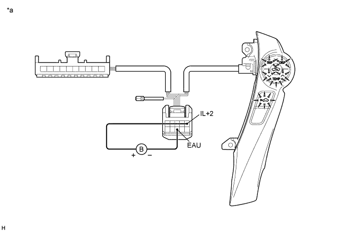
-
Connect a battery positive (+) lead to terminal IL+2 and a negative (-) lead to terminal EAU of the steering pad switch RH connector.
-
Check that the switch illumination comes on.
OK Steering pad switch illumination comes on. Tech Tips
If the result is not as specified, replace the steering pad switch RH.
Text in Illustration *a Component without harness connected
(Steering Pad Switch RH)
- -
-
-