STEERING COLUMN ASSEMBLY INSTALLATION

-
INSPECT STEERING COLUMN ASSEMBLY
-
Inspect the bushings.
-
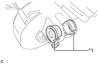
Text in Illustration *1 Bushing Check that the 2 bushings are securely installed to the steering column assembly.
If the 2 bushings are installed improperly, replace the steering column assembly with a new one.
-
Check the 2 bushings for deformation and damage.
If the bushings are deformed or damaged, replace the steering column assembly with a new one.
-
-
Inspect the capsules.
-
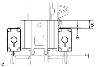
Text in Illustration *1 Capsule Check that the 2 capsules are securely installed to the steering column assembly as shown in the illustration.
Standard Dimension A B 2 mm (0.0787 in.) 17 mm (0.669 in.) If the capsules are not positioned as specified, replace the steering column assembly with a new one.
-
Check the 2 capsules for deformation and damage.
If either of the capsules is deformed, loose, missing or damaged, replace the steering column assembly with a new one.
-
-
-
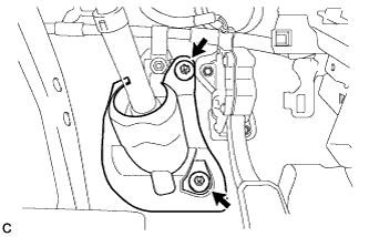
INSTALL NO. 1 STEERING COLUMN PROTECTOR (for RHD)
-
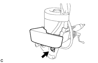
Install the No. 1 steering column protector to the steering column assembly with the bolt.
- Torque:
- 19 N*m { 189 kgf*cm, 14 ft.*lbf }
-
-
INSTALL NO. 2 STEERING INTERMEDIATE SHAFT ASSEMBLY
-
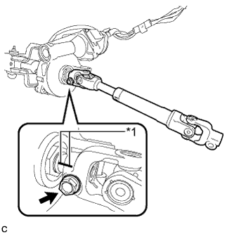
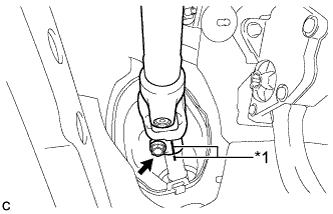
Text in Illustration *1 Matchmark Align the matchmarks on the No. 2 steering intermediate shaft assembly and steering column assembly to install the No. 2 steering intermediate shaft assembly.
-
Install the bolt.
- Torque:
- 35 N*m { 359 kgf*cm, 26 ft.*lbf }
-
-
INSTALL STEERING POST ASSEMBLY
-
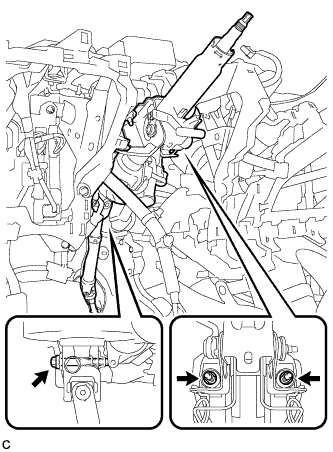
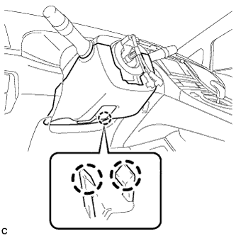
Install the steering post assembly with the bolt and 2 nuts.
- Torque:
- Bolt
- 36 N*m { 367 kgf*cm, 27 ft.*lbf }
- Nut
- 25 N*m { 255 kgf*cm, 18 ft.*lbf }
Note
There are two different bolt sizes (12 mm (0.472 in.) or 14 mm (0.551 in.)) available.
-
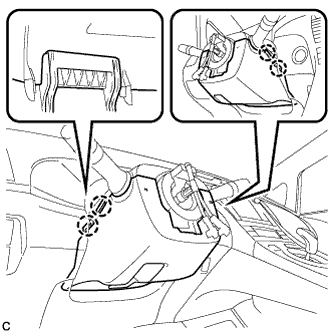
Connect the connectors and engage the wire harness clamps to the steering post assembly.
-
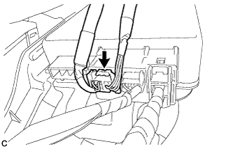
Connect the connector to the power steering ECU assembly.
-
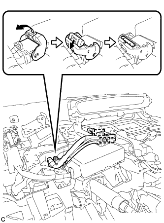
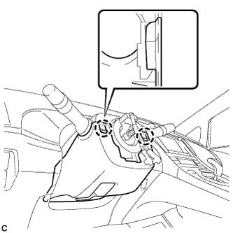
Connect the connector to the power steering ECU assembly.
Tech Tips
As shown in the illustration, securely return the lock lever to its original position to connect the connector.
-
Engage the 2 wire harness clamps.
-
-
CONNECT NO. 2 STEERING INTERMEDIATE SHAFT ASSEMBLY
-
Text in Illustration *1 Matchmark Align the matchmarks on the No. 2 steering intermediate shaft assembly and steering intermediate shaft to connect the No. 2 steering intermediate shaft assembly to the steering intermediate shaft.
-
Install the bolt.
- Torque:
- 35 N*m { 357 kgf*cm, 26 ft.*lbf }
-
-
INSTALL COLUMN HOLE COVER SILENCER SHEET
-
Install the column hole cover silencer sheet with the 2 clips.
-
Install the floor carpet.
-
-
INSTALL NO. 2 AIR DUCT SUB-ASSEMBLY
-
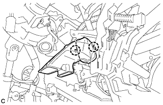
Engage the 2 claws to install the No. 2 air duct sub-assembly.
-
-
INSTALL NO. 1 HEATER TO REGISTER DUCT
-
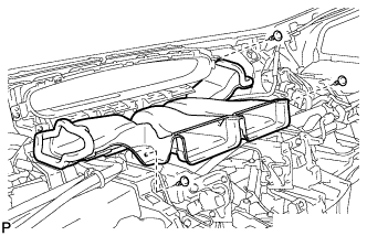
Install the No. 1 heater to register duct with the 3 clips.
-
-
INSTALL BRAKE PEDAL SUPPORT ASSEMBLY (for LHD)
Tech Tips
Refer to the instructions for Installation of the brake pedal support assembly Click here.
-
INSTALL BRAKE PEDAL SUPPORT ASSEMBLY (for RHD)
Tech Tips
Refer to the instructions for Installation of the brake pedal support assembly Click here.
-
INSTALL UPPER INSTRUMENT PANEL ASSEMBLY
Tech Tips
Refer to the instructions for Installation of the upper instrument panel assembly Click here.
-
INSTALL DRIVER SIDE KNEE AIRBAG ASSEMBLY
Tech Tips
Refer to the instructions for Installation of the driver side knee airbag assembly Click here.
-
ALIGN FRONT WHEELS FACING STRAIGHT AHEAD
-
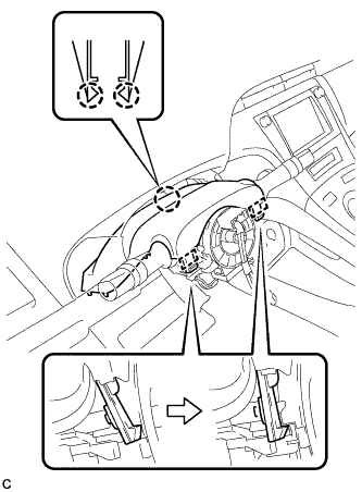
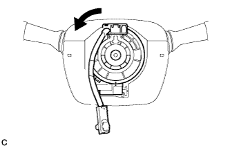
INSTALL TURN SIGNAL SWITCH ASSEMBLY WITH SPIRAL CABLE SUB-ASSEMBLY
-
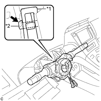
Text in Illustration *1 Clamp *2 Claw Using pliers, expand the clamp.
-
While holding the clamp expanded, install the turn signal switch assembly with spiral cable sub-assembly to the steering column assembly and engage the claw.
-
Return the clamp to its original position.
-
Connect the connectors to the turn signal switch assembly with spiral cable sub-assembly.
-
-
INSTALL UPPER STEERING COLUMN COVER
-
Engage the 2 claws and 2 pins to install the upper steering column cover.
-
-
INSTALL LOWER STEERING COLUMN COVER
Note
If the lower steering column cover is installed in the incorrect order, it will not be possible to assemble the lower steering column cover.
-
Engage the 2 claws to install the lower steering column cover.
-
Engage the 4 claws.
-
Engage the 2 claws.
Tech Tips
Press the area around the claws to engage them.
-
-
ALIGN FRONT WHEELS FACING STRAIGHT AHEAD
-
ADJUST SPIRAL CABLE WITH SENSOR SUB-ASSEMBLY
-
Check that the power switch is off.
-
Check that the cable is disconnected from the negative (-) battery terminal.
CAUTION:
Wait at least 90 seconds after disconnecting the cable from the negative (-) battery terminal to disable the SRS system.
-
Rotate the spiral cable counterclockwise slowly by hand until it stops.
Note
Do not turn the spiral cable using the airbag wire harness.
-
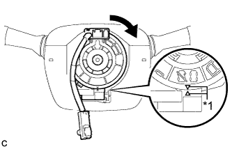
Text in Illustration *1 Alignment Mark Rotate the spiral cable clockwise approximately 2.5 turns to align the marks.
Note
Do not turn the spiral cable using the airbag wire harness.
Tech Tips
The spiral cable will rotate approximately 2.5 turns to both the left and right from the center.
-
-
INSTALL STEERING WHEEL ASSEMBLY
-
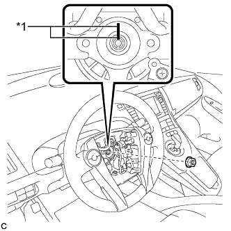
Text in Illustration *1 Matchmark Align the matchmarks on the steering wheel assembly and steering main shaft.
-
Install the steering wheel assembly set nut.
- Torque:
- 50 N*m { 510 kgf*cm, 37 ft.*lbf }
-
Connect the connectors to the spiral cable sub-assembly.
-
-
INSTALL STEERING PAD
Tech Tips
Refer to the instructions for Installation of the steering pad Click here.
-
ALIGN FRONT WHEELS FACING STRAIGHT AHEAD
-
CONNECT CABLE TO NEGATIVE BATTERY TERMINAL
Note
-
Connect the cable to the negative (-) battery terminal with the front wheels facing straight ahead.
-
When disconnecting the cable, some systems need to be initialized after the cable is reconnected Click here.
-
-
INSTALL REAR NO. 3 FLOOR BOARD
-

Engage the 2 guides to install the rear No. 3 floor board.
-
-
INSTALL REAR DECK FLOOR BOX
-
Install the rear deck floor box.
-
-
INSTALL REAR NO. 2 FLOOR BOARD
-

Engage the 3 guides <A>.
-
Engage the 2 guides <B> and install the rear No. 2 floor board as shown in the illustration.
-
-
INSPECT STEERING PAD
-

Visually check for defects with the steering pad installed on the vehicle.
-
The defects are as follows:
-
Cuts on the surface and in the grooves of the steering pad
-
Small cracks on the surface and in the grooves of the steering pad
-
Significant discoloration on the surface and in the grooves of the steering pad
OK No defects are found. Tech Tips
If any of the defects is found, replace the steering pad with a new one.
-
-
-
Make sure that the horn sounds.
Tech Tips
If the horn does not sound, inspect the horn system Click here.
-
-
INITIALIZE ROTATION ANGLE SENSOR AND CALIBRATE TORQUE SENSOR ZERO POINT
-
INSPECT SRS WARNING LIGHT
-
Inspect the SRS warning light Click here.
-