POWER STEERING SYSTEM, Diagnostic DTC:C1511, C1512, C1513, C1514, C1517

| DTC Code | DTC Name |
|---|---|
| C1511 | Torque Sensor Circuit Malfunction |
| C1512 | Torque Sensor Circuit Malfunction |
| C1513 | Torque Sensor Circuit Malfunction |
| C1514 | Torque Sensor Power Supply Abnormal |
| C1517 | Torque Hold Abnormal |
DESCRIPTION
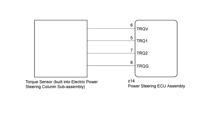
The torque sensor converts the rotation torque input from the steering wheel into electric signals and sends them to the power steering ECU assembly.
| DTC No. | DTC Detection Condition | Trouble Area |
|---|---|---|
| C1511 | Torque sensor malfunction |
|
| C1512 | ||
| C1513 | ||
| C1514 | ||
| C1517 |
WIRING DIAGRAM
INSPECTION PROCEDURE
Note
-
If the power steering ECU assembly has been replaced with a new one, perform rotation angle sensor initialization and torque sensor zero point calibration Click here.
-
If the electric power steering column sub-assembly or power steering motor assembly has been replaced, perform rotation angle sensor initialization and torque sensor zero point calibration Click here.
PROCEDURE
-
CHECK CONNECTOR CONNECTION CONDITION (TORQUE SENSOR - ECU)
-
Check the installation condition of the torque sensor connector.
OK Torque sensor connector is securely connected to the power steering ECU assembly.
NG 
CONNECT CONNECTOR
OK 
-
-
CHECK POWER STEERING ECU ASSEMBLY (TRQV VOLTAGE)
-
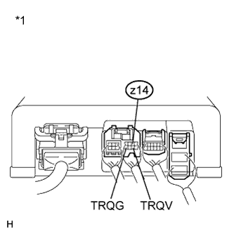
Text in Illustration *1 Component with harness connected
(Power Steering ECU Assembly)
Turn the power switch on (READY).
-
Measure the voltage according to the value(s) in the table below.
Standard Voltage Tester Connection Switch Condition Specified Condition z14-6 (TRQV) - z14-8 (TRQG) Power switch on (READY) 4.5 to 5.5 V
NG
REPLACE POWER STEERING ECU ASSEMBLY Click here
OK
-
-
CHECK POWER STEERING ECU ASSEMBLY (TRQ1, TRQ2 VOLTAGE)
-
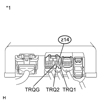
Text in Illustration *1 Component with harness connected
(Power Steering ECU Assembly)
Turn the power switch on (READY).
-
Measure the voltage according to the value(s) in the table below.
Standard Voltage Tester Connection Switch Condition (Steering Wheel Position) Specified Condition z14-5 (TRQ1) - z14-8 (TRQG) Power switch on (READY)
Steering wheel not turned (without load)
2.3 to 2.7 V Power switch on (READY)
Steering wheel turned to right with vehicle stopped
2.5 to 3.8 V Power switch on (READY)
Steering wheel turned to left with vehicle stopped
1.2 to 2.5 V z14-7 (TRQ2) - z14-8 (TRQG) Power switch on (READY)
Steering wheel not turned (without load)
2.3 to 2.7 V Power switch on (READY)
Steering wheel turned to right with vehicle stopped
1.2 to 2.5 V Power switch on (READY)
Steering wheel turned to left with vehicle stopped
2.5 to 3.8 V -
Under each condition, measure the voltage at terminals TRQ1 and TRQ2, and calculate the sum.
Standard Voltage Inspection Item Condition (Steering Wheel Position) Specified Condition Sum of voltage between z14-5 (TRQ1) and z14-8 (TRQG) and voltage between z14-7 (TRQ2) and z14-8 (TRQG) Power switch on (READY)
Steering wheel not being turned (without load)
Between 4.75 V and 5.25 V Power switch on (READY)
Steering wheel being turned to the right with vehicle stopped
Power switch on (READY)
Steering wheel being turned to the left with vehicle stopped
NG
REPLACE ELECTRIC POWER STEERING COLUMN SUB-ASSEMBLY Click here
OK 
REPLACE POWER STEERING ECU ASSEMBLY Click here
-