STEERING COLUMN ASSEMBLY REMOVAL

CAUTION:
Some of these service operations affect the SRS airbag system. Read the precautionary notices concerning the SRS airbag system before servicing Click here.
-
PRECAUTION
Note
Be sure to read Precaution thoroughly before servicing Click here.
-
ALIGN FRONT WHEELS FACING STRAIGHT AHEAD
-
REMOVE STEERING PAD
Tech Tips
Refer to the instructions for Removal of the steering pad Click here.
-
REMOVE STEERING WHEEL ASSEMBLY
-
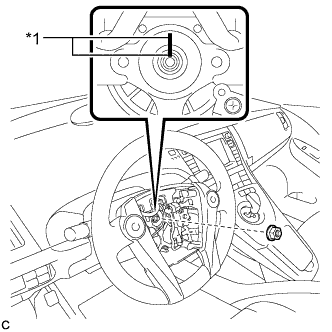
Text in Illustration *1 Matchmark Remove the steering wheel assembly set nut.
-
Put matchmarks on the steering wheel assembly and steering main shaft.
-
Disconnect the connectors from the spiral cable.
-
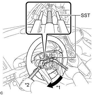
Text in Illustration *1 Turn *2 Hold Using SST, remove the steering wheel assembly.
- SST
- 09950-50013 ( 09951-05010, 09952-05010, 09953-05020, 09955-04071 )
Note
Apply a small amount of grease to the threads and tip of SST (09953-05020) before use.
-
-
REMOVE LOWER STEERING COLUMN COVER
Note
Removing the lower steering column cover in the incorrect order will cause the parts to break.
-
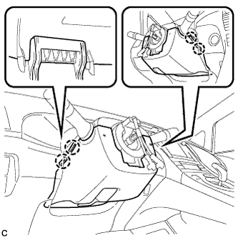
Push the right and left sides of the lower steering column cover to disengage the 4 claws.
-
Insert fingers into the opening of the tilt lever of the lower steering column cover to disengage the 2 claws.
Tech Tips
Spread the claws to disengage them.
-
Using a screwdriver, insert the tip into each service hole to disengage the 2 claws to remove the lower steering column cover as shown in the illustration.
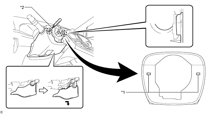
Text in Illustration *1 Service Hole *2 Protective Tape Tech Tips
Tape the screwdriver tip before use.
-
-
REMOVE UPPER STEERING COLUMN COVER
-
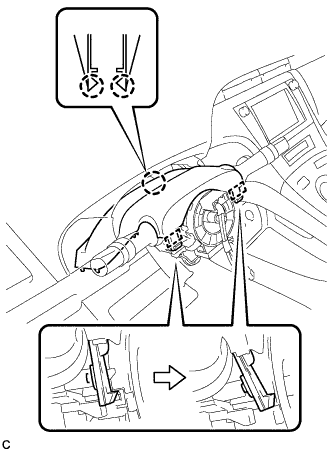
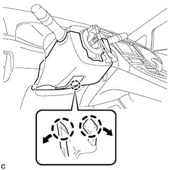
Disengage the 2 claws and 2 pins to remove the upper steering column cover.
-
-
REMOVE TURN SIGNAL SWITCH ASSEMBLY WITH SPIRAL CABLE SUB-ASSEMBLY
-
Disconnect the connectors from the turn signal switch assembly with spiral cable sub-assembly.
-
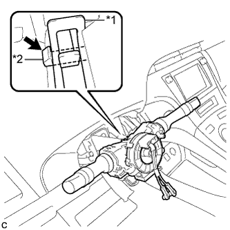
Text in Illustration *1 Clamp *2 Claw Using pliers, expand the clamp.
-
While holding the clamp expanded, raise the claw using a screwdriver to disengage it, and then remove the turn signal switch assembly with spiral cable sub-assembly from the steering column assembly.
-
-
REMOVE DRIVER SIDE KNEE AIRBAG ASSEMBLY
Tech Tips
Refer to the instructions for Removal of the driver side knee airbag assembly Click here.
-
REMOVE UPPER INSTRUMENT PANEL ASSEMBLY
Tech Tips
Refer to the instructions for Removal of the upper instrument panel assembly Click here.
-
REMOVE BRAKE PEDAL SUPPORT ASSEMBLY (for LHD)
Tech Tips
Refer to the instructions for Removal of the brake pedal support assembly Click here.
-
REMOVE BRAKE PEDAL SUPPORT ASSEMBLY (for RHD)
Tech Tips
Refer to the instructions for Removal of the brake pedal support assembly Click here.
-
REMOVE NO. 1 HEATER TO REGISTER DUCT
-
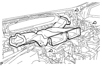
Remove the 3 clips and the No. 1 heater to register duct.
-
-
REMOVE NO. 2 AIR DUCT SUB-ASSEMBLY
-
Disengage the 2 claws to remove the No. 2 air duct sub-assembly.
-
-
REMOVE COLUMN HOLE COVER SILENCER SHEET
-
Turn back the floor carpet.
-
Remove the 2 clips and column hole cover silencer sheet.
-
-
SEPARATE NO. 2 STEERING INTERMEDIATE SHAFT ASSEMBLY
-
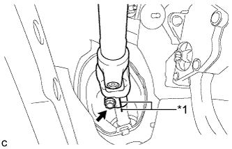
Text in Illustration *1 Matchmark Put matchmarks on the No. 2 steering intermediate shaft assembly and steering intermediate shaft.
Note
Do not separate the No. 2 steering intermediate shaft assembly from the steering intermediate shaft.
-
Remove the bolt.
-
Separate the No. 2 steering intermediate shaft assembly from the steering intermediate shaft.
-
-
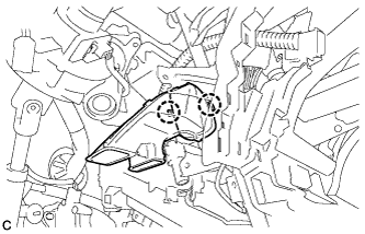
REMOVE STEERING POST ASSEMBLY
-
Disengage the 2 wire harness clamps.
-
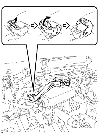
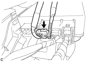
Disconnect the connector from the power steering ECU assembly.
Tech Tips
As shown in the illustration, turn the lock lever to disconnect the connector.
-
Disconnect the connector from the power steering ECU assembly.
-
Disconnect the connectors and disengage the wire harness clamps from the steering post assembly.
-
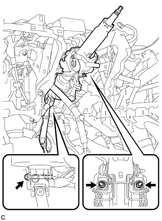
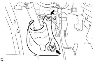
Remove the bolt, 2 nuts and steering post assembly.
-
-
REMOVE NO. 2 STEERING INTERMEDIATE SHAFT ASSEMBLY
-
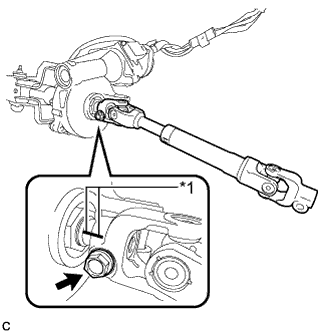
Text in Illustration *1 Matchmark Put matchmarks on the No. 2 steering intermediate shaft assembly and steering column assembly.
-
Remove the bolt and No. 2 steering intermediate shaft assembly from the steering column assembly.
-
-
REMOVE NO. 1 STEERING COLUMN PROTECTOR (for RHD)
-
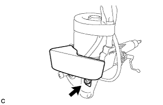
Remove the bolt and No. 1 steering column protector from the steering column assembly.
-