PARKING BRAKE PEDAL (for RHD) INSTALLATION

-
INSTALL PARKING BRAKE CONTROL PEDAL ASSEMBLY
-
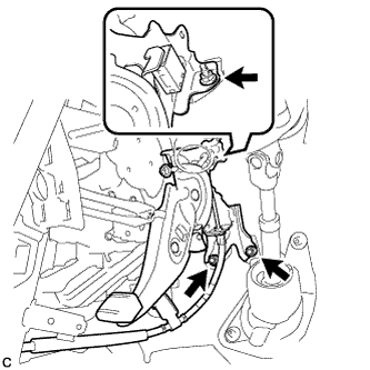
Install the parking brake control pedal assembly with the 2 bolts and nut.
- Torque:
- 15 N*m { 148 kgf*cm, 11 ft.*lbf }
-
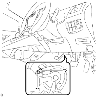
Connect the parking brake switch connector.
-
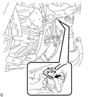
Engage the wire harness clamp.
-
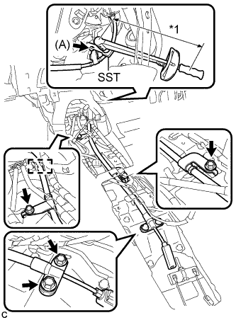
Text in Illustration *1 Fulcrum Length Using SST, install the bolt (A).
- SST
- 09961-00950
- Torque:
- Without SST
- 15 N*m { 148 kgf*cm, 11 ft.*lbf }
- With SST
- 9.4 N*m { 96 kgf*cm, 83 in.*lbf }
Note
-
Use a torque wrench with a fulcrum length of 250 mm (9.84 in.).
-
This torque value is effective when SST is parallel to the torque wrench.
-
Install the No. 1 parking brake cable assembly with the 4 bolts.
- Torque:
- 15 N*m { 148 kgf*cm, 11 ft.*lbf }
-
Engage the clamp.
-
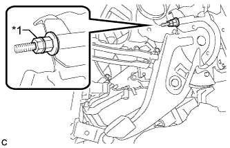
Text in Illustration *1 Lock Nut Temporarily install the lock nut.
Tech Tips
After adjusting parking brake pedal travel, tighten the lock nut.
-
-
CONNECT NO. 1 PARKING BRAKE PULL ROD SUB-ASSEMBLY
-
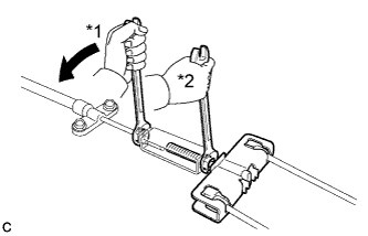
Text in Illustration *1 Turn *2 Hold Connect the No. 1 parking brake pull rod sub-assembly to the parking brake control pedal assembly as shown in the illustration.
- Torque:
- 5.4 N*m { 55 kgf*cm, 48 in.*lbf }
-
-
INSTALL NO. 2 AIR DUCT SUB-ASSEMBLY
-
Engage the 2 claws to install the No. 2 air duct sub-assembly.
-
-
INSTALL NO. 3 BELT ANCHOR REINFORCEMENT SUB-ASSEMBLY
-
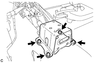
Install the No. 3 belt anchor reinforcement subassembly with the 4 bolts.
- Torque:
- 27 N*m { 275 kgf*cm, 20 ft.*lbf }
-
-
INSTALL NO. 2 BELT ANCHOR REINFORCEMENT SUB-ASSEMBLY
-
Install the No. 2 belt anchor reinforcement subassembly with the 4 bolts.
- Torque:
- 27 N*m { 275 kgf*cm, 20 ft.*lbf }
-
-
INSTALL YAW RATE AND ACCELERATION SENSOR
-
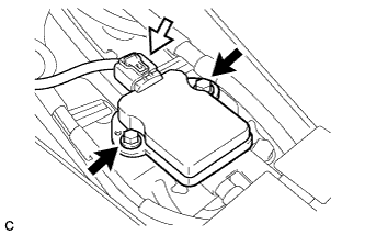
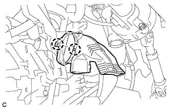
Connect the yaw rate and acceleration sensor connector.
Note
Make sure that the yaw rate and acceleration sensor connector is connected securely.
-
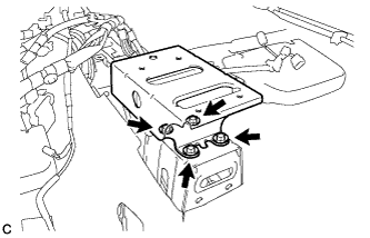
Install the yaw rate and acceleration sensor with the 2 bolts.
- Torque:
- 8.5 N*m { 87 kgf*cm, 75 in.*lbf }
Note
-
Do not damage the yaw rate and acceleration sensor.
-
Make sure that the yaw rate and acceleration sensor is installed securely.
-
Do not use dropped or damaged parts.
-
Keep the contact surfaces of the yaw rate and acceleration sensor and the body free of foreign matter.
-
Make sure that the sensor is facing the correct direction.
-
-
INSTALL FRONT SEAT ASSEMBLY RH
-
for Manual Seat:
Tech Tips
This is symmetrical to the LHD model Click here.
-
for Power Seat:
-
-
INSTALL FRONT SEAT ASSEMBLY LH
Tech Tips
Perform the same procedure as for the RH side.
-
INSTALL DRIVER SIDE KNEE AIRBAG ASSEMBLY
Tech Tips
This is symmetrical to the LHD model Click here.
-
ADJUST PARKING BRAKE PEDAL TRAVEL
-
Remove the No. 2 instrument panel under cover sub-assembly.
Tech Tips
This is symmetrical to the LHD model Click here.
-
Completely release the parking brake pedal.
-
Text in Illustration *1 Lock Nut *2 Adjusting Nut Loosen the lock nut and the adjusting nut to completely release the parking brake cable.
-
Turn the adjusting nut until the parking brake pedal travel is corrected to be within the specified range.
Parking brake pedal travel 8 to 11 notches at 300 N (31 kgf, 67.5 lbf) -
Text in Illustration *1 Lock Nut *2 Adjusting Nut Using a wrench or an equivalent tool, hold the adjusting nut and tighten the lock nut.
- Torque:
- 5.4 N*m { 55 kgf*cm, 48 in.*lbf }
-
Operate the parking brake pedal 3 to 4 times, and check the parking brake pedal travel.
-
Check whether the parking brake drags or not.
-
Install the No. 2 instrument panel under cover sub-assembly.
Tech Tips
This is symmetrical to the LHD model Click here.
-
-
INSPECT BRAKE WARNING LIGHT
-
When operating the parking brake pedal, check that the brake warning light illuminates.
Standard The brake warning light always illuminates at the first click.
-