REAR BRAKE FLEXIBLE HOSE INSTALLATION

Note
-
Because the left and right rear flexible hoses are not interchangeable, verify the part number when installing the flexible hoses.
-
If the hoses are to be reused, connect them after checking the identification marks placed when each hose was disconnected.
Tech Tips
-
Use the same procedure for the LH side and RH side.
-
The following procedure is for the LH side.
-
INSTALL REAR BRAKE TUBE FLEXIBLE HOSE (for LH Side)
-
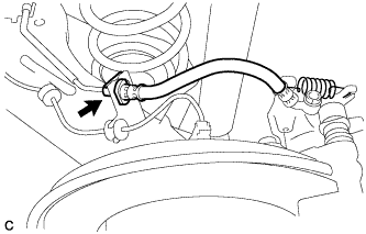
Install the rear brake tube flexible hose with the bolt and a new clip.
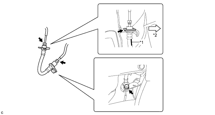
Text in Illustration *1 Identification Mark *2 Inside of the Vehicle - Torque:
- 19 N*m { 194 kgf*cm, 14 ft.*lbf }
Note
-
Install the clip as far as it will go.
-
When installing the rear brake tube flexible hose, face the identification mark to the inside of the vehicle and minimize twisting of the hose.
-
Using a union nut wrench, connect the 2 brake lines to the rear brake tube flexible hose.
- Torque:
- 15 N*m { 155 kgf*cm, 11 ft.*lbf }
Note
-
Do not bend or damage the brake line.
-
Do not allow any foreign matter such as dirt and dust to enter the brake line from the connecting points.
-
Use the formula to calculate special torque values for situations where the union nut wrench is combined with a torque wrench Click here.
-
-
INSTALL REAR BRAKE TUBE FLEXIBLE HOSE (for RH Side)
-
Install the rear brake tube flexible hose with 2 new clips.
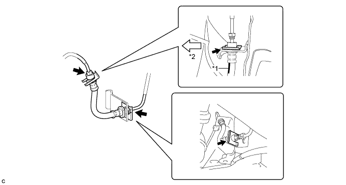
Text in Illustration *1 Identification Mark *2 Inside of the Vehicle Note
-
Install the clip as far as it will go.
-
When installing the rear brake tube flexible hose, face the identification mark to the inside of the vehicle and minimize twisting of the hose.
-
-
Using a union nut wrench, connect the 2 brake lines to the rear brake tube flexible hose.
- Torque:
- 15 N*m { 155 kgf*cm, 11 ft.*lbf }
Note
-
Do not bend or damage the brake line.
-
Do not allow any foreign matter such as dirt and dust to enter the brake line from the connecting points.
-
Use the formula to calculate special torque values for situations where the union nut wrench is combined with a torque wrench Click here.
-
-
INSTALL REAR FLEXIBLE HOSE
-
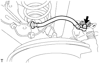
Connect the rear flexible hose to the rear disc brake cylinder assembly with a new union bolt and a new gasket.
- Torque:
- 33 N*m { 340 kgf*cm, 25 ft.*lbf }
-
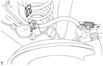
Install a new clip.
Note
Install the clip as far as it will go.
-
Using a union nut wrench, connect the brake line to the rear flexible hose while holding the rear flexible hose with a wrench.
- Torque:
- 15 N*m { 155 kgf*cm, 11 ft.*lbf }
Note
-
Do not bend or damage the brake line.
-
Do not allow any foreign matter such as dirt and dust to enter the brake line from the connecting points.
-
Use the formula to calculate special torque values for situations where the union nut wrench is combined with a torque wrench Click here.
-
-
FILL RESERVOIR WITH BRAKE FLUID
-
CONNECT CABLE TO NEGATIVE BATTERY TERMINAL
Note
When disconnecting the cable, some systems need to be initialized after the cable is reconnected Click here.
-
INSTALL REAR NO. 3 FLOOR BOARD
-

Engage the 2 guides to install the rear No. 3 floor board.
-
-
INSTALL REAR DECK FLOOR BOX
-
Install the rear deck floor box.
-
-
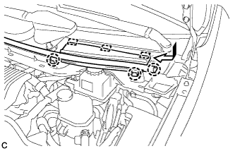
INSTALL REAR NO. 2 FLOOR BOARD
-

Engage the 3 guides <A>.
-
Engage the 2 guides <B> and install the rear No. 2 floor board as shown in the illustration.
-
-
BLEED BRAKE LINE
-
Remove the center cowl top ventilator cover.
-
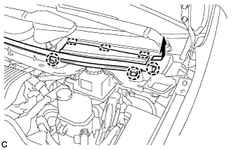
Slide the hood to cowl top seal and disengage the claw.
-
Disengage the 2 claws and 3 guides, and remove the center cowl top ventilator cover.
-
-
Bleed brake line.
-
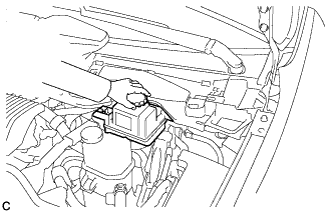
Remove the brake master cylinder reservoir filler cap assembly.
-
Add brake fluid into the reservoir between MAX and MIN level on the brake fluid reservoir.
Brake fluid SAE J1703 or FMVSS No. 116 DOT3 -
Connect the intelligent tester to the DLC3 and turn the power switch on (IG).
-
Turn the intelligent tester on and enter the following menus: Chassis / ABS/VSC/TRC / Air Bleeding.
-
Select the "Usual air bleeding" on the intelligent tester display, and bleed air from the brake fluid following the instructions on the intelligent tester.
-
After air bleeding, tighten each bleeder plug.
- Torque:
- front bleeder plug
- 8.3 N*m { 85 kgf*cm, 73 in.*lbf }
- rear bleeder plug
- 11 N*m { 112 kgf*cm, 8 ft.*lbf }
-
Clear the DTCs Click here.
-
Turn the intelligent tester off and turn the power switch off.
-
-
Inspect for brake fluid leaks.
-
Install the brake master cylinder reservoir filler cap.
-
Install the center cowl top ventilator cover.
-
Engage the 2 claws and 3 guides to install the center cowl top ventilator cover.
-
Slide the hood to cowl top seal to engage the claw.
-
-
-
INSTALL REAR WHEEL
- Torque:
- 103 N*m { 1050 kgf*cm, 76 ft.*lbf }