REAR BRAKE INSTALLATION

Tech Tips
-
Use the same procedure for the LH side and RH side.
-
The following procedure is for the LH side.
-
INSTALL REAR DISC
-
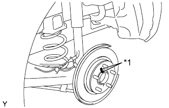
Text in Illustration *1 Matchmark Align the matchmarks of the disc and axle hub, and install the disc.
Note
When replacing the disc with a new one, select the installation position where the rear disc has minimal runout.
-
-
INSTALL REAR DISC BRAKE CYLINDER MOUNTING
-
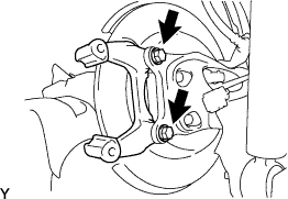
Install the rear disc brake cylinder mounting to the axle beam with the 2 bolts.
- Torque:
- 57 N*m { 585 kgf*cm, 42 ft.*lbf }
-
-
INSTALL REAR DISC BRAKE BUSHING DUST BOOT
-
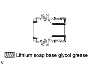
Apply a light layer of lithium soap base glycol grease to the entire circumference of 2 new rear disc brake bushing dust boots.
Tech Tips
Apply at least 0.3 g (0.01 oz.) of lithium soap base glycol grease to each rear disc brake bushing dust boot.
-
Install the 2 rear disc brake bushing dust boots to the rear disc brake cylinder mounting.
-
-
INSTALL REAR DISC BRAKE PAD GUIDE PIN
-
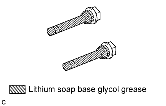
Apply a light layer of lithium soap base glycol grease to the sliding and sealing surfaces of the 2 rear disc brake pad guide pins.
-
Install the 2 rear disc brake pad guide pins to the rear disc brake cylinder mounting.
-
-
INSTALL REAR DISC BRAKE PAD SUPPORT PLATE
-

Install the 2 rear disc brake pad support plates to the rear disc brake cylinder mounting.
Note
Be sure to install each rear disc brake pad support plate in the correct position and direction.
-
-
INSTALL REAR DISC BRAKE ANTI-SQUEAL SHIM
-
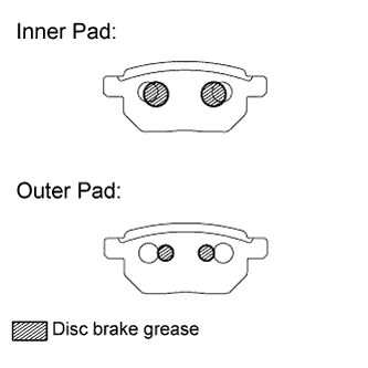
Apply disc brake grease to the back plate of the rear disc brake pads.
-
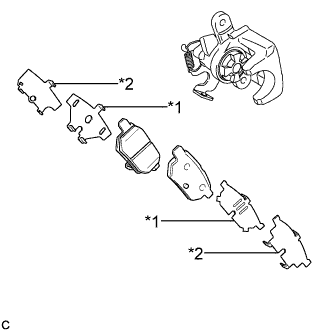
Text in Illustration *1 Rear No. 1 Disc Brake Anti-squeal Shim *2 Rear No. 2 Disc Brake Anti-squeal Shim Install the rear No. 1 disc brake anti-squeal shim and rear No. 2 disc brake anti-squeal shim to each rear disc brake pad.
Note
-
When replacing worn pads, the anti-squeal shims must be replaced together with the pads.
-
Apply disc brake grease to the area that contacts the anti-squeal shim.
-
Disc brake grease may seep out slightly from the areas where the anti-squeal shims are installed.
-
Make sure that disc brake grease is not applied onto the lining surface.
-
-
-
INSTALL REAR DISC BRAKE PAD
-
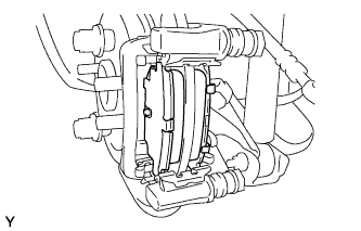
Install the 2 rear disc brake pads to the rear disc brake cylinder mounting.
Note
There should be no oil or grease on the friction surfaces of the disc brake pads or the rear disc.
-
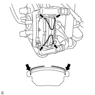
Install the 2 anti-squeal springs to the rear disc brake pads.
Note
-
When replacing the rear disc brake pads with new ones, make sure to replace the anti-squeal springs at the same time.
-
Be sure to install the anti-squeal springs into the rear disc brake pad installation holes as far as they will go.
-
-
-
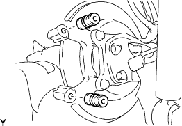
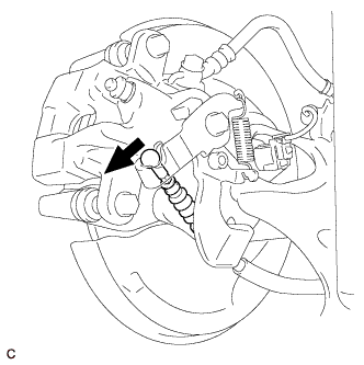
INSTALL REAR DISC BRAKE CYLINDER ASSEMBLY
-
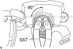
To compensate for pad wear when reusing the pad, use SST to turn the piston to the position where the protrusion on the pad lines up properly with the piston groove.
Retract Extend Clockwise Counterclockwise - SST
- 09960-10010 ( 09963-00400 )
Note
Place the disc between the 2 brake pads and determine the piston return value.
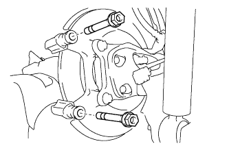
-
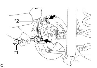
Text in Illustration *1 Hold *2 Turn Hold the rear disc brake cylinder pad guide pin, and install the rear disc brake cylinder assembly to the rear disc brake cylinder mounting with the 2 bolts.
- Torque:
- 34 N*m { 350 kgf*cm, 25 ft.*lbf }
Note
-
Install the rear disc brake cylinder assembly while holding both of the rear disc brake pads because the anti-squeal springs may fall off the rear disc brake pads.
-
Be sure that the anti-squeal springs are installed to the rear disc brake pads.
-
-
CONNECT REAR FLEXIBLE HOSE
-
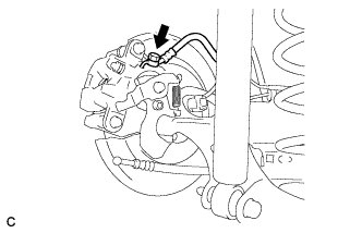
Connect the rear flexible hose to the rear disc brake cylinder assembly with a new union bolt and a new gasket.
- Torque:
- 33 N*m { 340 kgf*cm, 25 ft.*lbf }
Tech Tips
Install the flexible hose lock securely into the lock hole in the disc brake cylinder.
-
-
CONNECT NO. 3 PARKING BRAKE CABLE ASSEMBLY
-
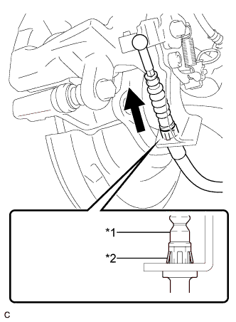
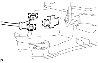
Text in Illustration *1 No. 3 Parking Brake Cable Assembly *2 Clip Install the No. 3 parking brake cable assembly to the rear disc brake cylinder assembly.
Tech Tips
Be sure to engage the No. 3 parking brake cable assembly clip onto the rear disc brake cylinder assembly as shown in the illustration.
-
Connect the No. 3 parking brake cable assembly to the rear disc brake cylinder assembly.
-
-
FILL RESERVOIR WITH BRAKE FLUID
-
CONNECT CABLE TO NEGATIVE BATTERY TERMINAL
-
Connect the cable to the negative (-) battery terminal.
Note
When disconnecting the cable, some systems need to be initialized after the cable is reconnected Click here.
-
Perform the following procedure if air bleeding is not necessary:
-
Connect the reservoir level switch connector.
-
Clear the DTCs Click here.
-
-
-
INSTALL REAR NO. 3 FLOOR BOARD
-

Engage the 2 guides to install the rear No. 3 floor board.
-
-
INSTALL REAR DECK FLOOR BOX
-
Install the rear deck floor box.
-
-
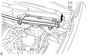
INSTALL REAR NO. 2 FLOOR BOARD
-

Engage the 3 guides <A>.
-
Engage the 2 guides <B> and install the rear No. 2 floor board as shown in the illustration.
-
-
BLEED BRAKE LINE
-
Remove the center cowl top ventilator cover.
-
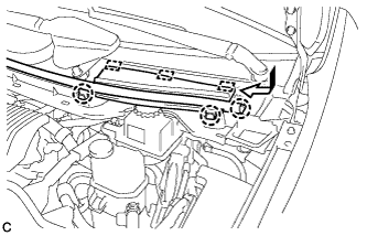
Slide the hood to cowl top seal and disengage the claw.
-
Disengage the 2 claws and 3 guides, and remove the center cowl top ventilator cover.
-
-
Bleed brake line.
-
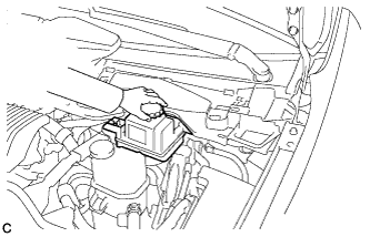
Remove the brake master cylinder reservoir filler cap assembly.
-
Add brake fluid into the reservoir between MAX and MIN level on the brake fluid reservoir.
Brake fluid SAE J1703 or FMVSS No. 116 DOT3 -
Connect the intelligent tester to the DLC3 and turn the power switch on (IG).
-
Turn the intelligent tester on and enter the following menus: Chassis / ABS/VSC/TRC / Air Bleeding.
-
Select the "Usual air bleeding" on the intelligent tester display, and bleed air from the brake fluid following the instructions on the intelligent tester.
-
After air bleeding, tighten each bleeder plug.
- Torque:
- front bleeder plug
- 8.3 N*m { 85 kgf*cm, 73 in.*lbf }
- rear bleeder plug
- 11 N*m { 112 kgf*cm, 8 ft.*lbf }
-
Clear the DTCs Click here.
-
Turn the intelligent tester off and turn the power switch off.
-
-
Inspect for brake fluid leaks.
-
Install the brake master cylinder reservoir filler cap.
-
Install the center cowl top ventilator cover.
-
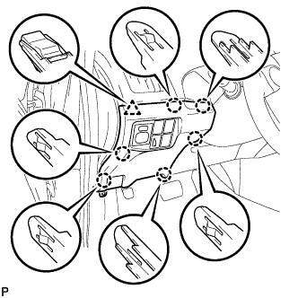
Engage the 2 claws and 3 guides to install the center cowl top ventilator cover.
-
Slide the hood to cowl top seal to engage the claw.
-
-
-
ADJUST PARKING BRAKE
Tech Tips
-
INSTALL LOWER INSTRUMENT PANEL FINISH PANEL ASSEMBLY (for LHD)
-
Connect each connector.
-
Engage the clamp.
-
Engage the 2 guides and claw to connect the hood lock control cable.
-
Engage the 6 claws and clip.
-
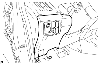
Install the lower instrument panel finish panel assembly with the screw <C>.
-
-
INSTALL COWL SIDE TRIM SUB-ASSEMBLY LH (for LHD)
-
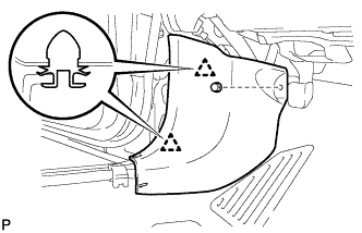
Engage the 2 clips.
-
Install the cowl side trim board LH with the clip.
-
-
INSTALL FRONT DOOR SCUFF PLATE LH (for LHD)
-
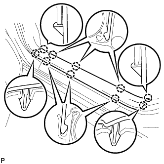
Engage the 10 claws to install the front door scuff plate LH.
-
-
INSTALL NO. 1 INSTRUMENT PANEL UNDER COVER SUB-ASSEMBLY (for RHD)
-
Connect each connector.
-
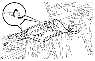
Engage the guide and 2 claws.
-
Install the No. 1 instrument panel under cover sub-assembly with the screw <D>.
-
-
INSTALL REAR WHEEL
- Torque:
- 103 N*m { 1050 kgf*cm, 76 ft.*lbf }