LIGHTING SYSTEM Light Control Switch Circuit
DESCRIPTION
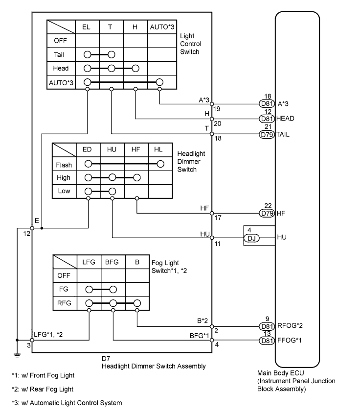
The main body ECU receives light control switch, dimmer switch and fog light switch information signals from the headlight dimmer switch.
WIRING DIAGRAM
INSPECTION PROCEDURE
PROCEDURE
-
READ VALUE USING INTELLIGENT TESTER (HEADLIGHT DIMMER SWITCH)
-
Connect the intelligent tester to the DLC3.
-
Turn the ignition switch to ON.
-
Turn the intelligent tester on.
-
Enter the following menus: Body / Main Body / Data List.
-
According to the display on the intelligent tester, read the Data List.
Main Body Tester Display Measurement Item/Range Normal Condition Diagnostic Note Dimmer SW Dimmer switch signal / ON or OFF ON: Dimmer switch on
OFF: Dimmer switch off
- Passing Light SW Passing light switch signal / ON or OFF ON: Passing light switch on
OFF: Passing light switch off
- Front Fog Light SW*1 Front fog light switch signal / ON or OFF ON: Front fog light switch on
OFF: Front fog light switch off
- Rear Fog Light SW*2 Rear fog light switch signal / ON or OFF ON: Rear fog light switch on
OFF: Rear fog light switch off
- Auto Light SW*3 Auto light switch signal / ON or OFF ON: Auto light switch on
OFF: Auto light switch off
- Head Light SW (Head) Headlight switch signal / ON or OFF ON: Headlight switch on
OFF: Headlight switch off
- Head Light SW (Tail) Taillight switch signal / ON or OFF ON: Taillight switch on
OFF: Taillight switch off
- *1: w/ Front Fog Light
*2: w/ Rear Fog Light
*3: w/ Automatic Light Control System
OK Tester display changes according to operation of each switch in the headlight dimmer switch.
NG 
INSPECT HEADLIGHT DIMMER SWITCH ASSEMBLY Click here
OK 
PROCEED TO NEXT SUSPECTED AREA SHOWN IN PROBLEM SYMPTOMS TABLE Click here
-
-
INSPECT HEADLIGHT DIMMER SWITCH ASSEMBLY
-
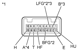
Text in Illustration *1 Component without harness connected
(Headlight Dimmer Switch Assembly)
*2 w/ Front Fog Light *3 w/ Rear Fog Light *4 w/ Automatic Light Control System Remove the headlight dimmer switch Click here.
-
Measure the resistance according to the value(s) in the table below.
Standard Resistance Tester Connection Switch Condition Specified Condition 18 (T) - 12 (E) Light control switch TAIL Below 1 Ω Light control switch HEAD Below 1 Ω 20 (H) - 12 (E) Light control switch HEAD Below 1 Ω 19 (A) - 12 (E) Light control switch AUTO Below 1 Ω 4 (BFG) - 3 (LFG) Front fog light switch on Below 1 Ω 2 (B) - 3 (LFG) Rear fog light switch on Below 1 Ω 17 (HF) - 12 (E) Dimmer switch high Below 1 Ω 11 (HU) - 12 (E) Dimmer switch low Below 1 Ω
NG 
REPLACE HEADLIGHT DIMMER SWITCH ASSEMBLY Click here
OK 
-
-
CHECK HARNESS AND CONNECTOR (HEADLIGHT DIMMER SWITCH ASSEMBLY - MAIN BODY ECU AND BODY GROUND)
-
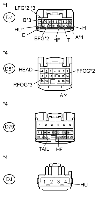
Text in Illustration *1 Front view of wire harness connector
(to Headlight Dimmer Switch Assembly)
*2 w/ Front Fog Light *3 w/ Rear Fog Light *4 w/ Automatic Light Control System *5 Front view of wire harness connector
(to Main Body ECU)
Disconnect the D7 headlight dimmer switch connector.
-
Disconnect the D81, D79, and DJ main body ECU connectors.
-
Measure the resistance according to the value(s) in the table below.
Standard Resistance Tester Connection Condition Specified Condition D7-4 (BFG) - D81-13 (FFOG) Always Below 1 Ω D7-2 (B) - D81-9 (RFOG) Always Below 1 Ω D7-19 (A) - D81-18 (A) Always Below 1 Ω D7-20 (H) - D81-12 (HEAD) Always Below 1 Ω D7-18 (T) - D79-21 (TAIL) Always Below 1 Ω D7-17 (HF) - D79-22 (HF) Always Below 1 Ω D7-11 (HU) - DJ-4 (HU) Always Below 1 Ω D7-4 (BFG) - Body ground Always 10 kΩ or higher D7-2 (B) - Body ground Always 10 kΩ or higher D7-19 (A) - Body ground Always 10 kΩ or higher D7-20 (H) - Body ground Always 10 kΩ or higher D7-18 (T) - Body ground Always 10 kΩ or higher D7-17 (HF) - Body ground Always 10 kΩ or higher D7-11 (HU) - Body ground Always 10 kΩ or higher D7-12 (E) - Body ground Always Below 1 Ω D7-3 (LFG) - Body ground Always Below 1 Ω
NG
REPAIR OR REPLACE HARNESS OR CONNECTOR
OK
REPLACE MAIN BODY ECU
-