LIGHTING SYSTEM Taillight Circuit
DESCRIPTION
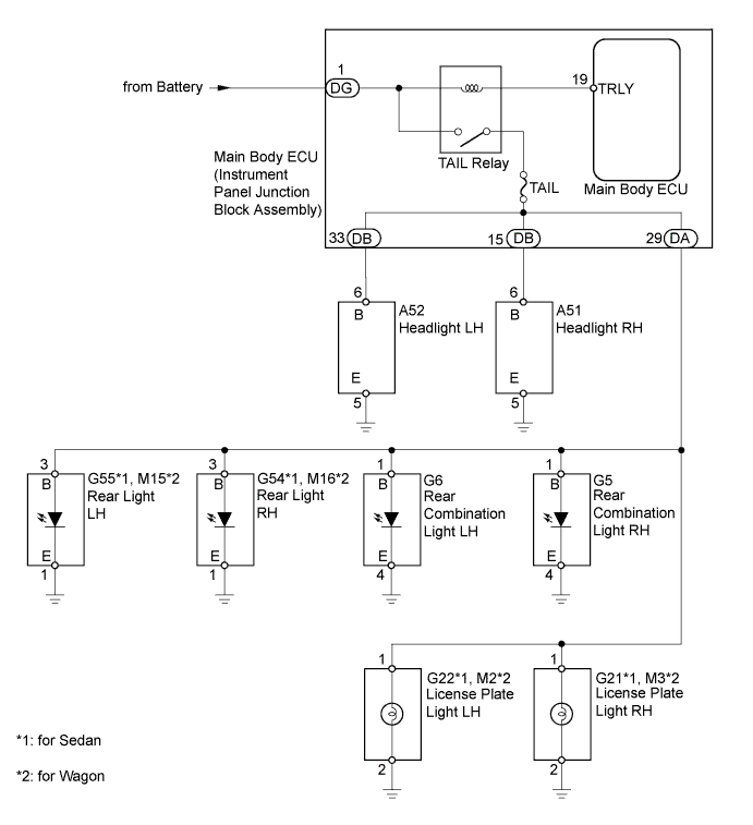
The main body ECU receives a light control switch information signal from the headlight dimmer switch, and illuminates the taillights, front clearance lights and license plate lights.
WIRING DIAGRAM
INSPECTION PROCEDURE
Tech Tips
Inspect the fuses and bulbs for circuits related to this system before performing the following inspection procedure.
PROCEDURE
-
PERFORM ACTIVE TEST USING INTELLIGENT TESTER (TAILLIGHT)
-
Connect the intelligent tester to the DLC3.
-
Turn the ignition switch to ON.
-
Turn the intelligent tester on.
-
Enter the following menus: Body / Main Body / Active Test / Tail Light.
-
Check that the taillights, front clearance lights and license plate lights turn on/off.
Main Body Tester Display Test Part Control Range Diagnostic Note Taillight Relay Taillight ON or OFF - OK Taillights, front clearance lights and license plate lights turn on/off. Result Result Proceed to OK A NG (Taillights, front clearance lights and license plate lights do not turn on) B NG (Front clearance lights do not turn on) C NG (Taillights and license plate lights do not turn on) D
B 
CHECK HARNESS AND CONNECTOR (MAIN BODY ECU - BATTERY) Click here
C
INSPECT MAIN BODY ECU (INSTRUMENT PANEL JUNCTION BLOCK ASSEMBLY) Click here
D
INSPECT MAIN BODY ECU (INSTRUMENT PANEL JUNCTION BLOCK ASSEMBLY) Click here
A 
PROCEED TO NEXT SUSPECTED AREA SHOWN IN PROBLEM SYMPTOMS TABLE Click here
-
-
CHECK HARNESS AND CONNECTOR (MAIN BODY ECU - BATTERY)
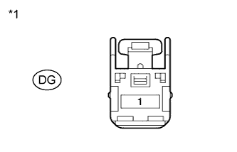
Text in Illustration *1 Front view of wire harness connector
(to Main Body ECU)
-
Disconnect the DG main body ECU connector.
-
Measure the voltage according to the value(s) in the table below.
Standard Voltage Tester Connection Condition Specified Condition DG-1 - Body ground Always 11 to 14 V
NG 
REPAIR OR REPLACE HARNESS OR CONNECTOR
OK
REPLACE MAIN BODY ECU (INSTRUMENT PANEL JUNCTION BLOCK ASSEMBLY)
-
-
INSPECT MAIN BODY ECU (INSTRUMENT PANEL JUNCTION BLOCK ASSEMBLY)
-
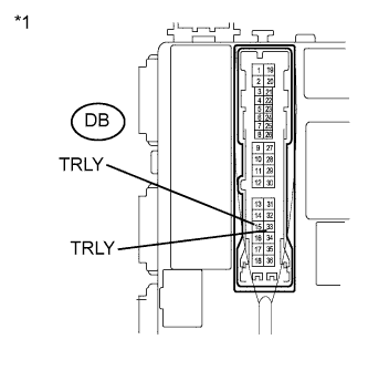
Text in Illustration *1 Component with harness connected
(Main Body ECU)
Remove the main body ECU with its connector still connected.
-
Measure the voltage according to the value(s) in the table below.
Standard Voltage Tester Connection Switch Condition Specified Condition DB-15 (TRLY) - Body Ground Light control switch
off → TAIL
Below 1 V → 11 to 14 V DB-33 (TRLY) - Body Ground Light control switch
off → TAIL
Below 1 V → 11 to 14 V
NG
REPLACE MAIN BODY ECU (INSTRUMENT PANEL JUNCTION BLOCK ASSEMBLY)
OK 
-
-
CHECK HARNESS AND CONNECTOR (HEADLIGHT [FRONT CLEARANCE LIGHT] - MAIN BODY ECU AND BODY GROUND)
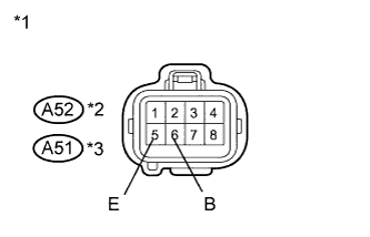
Text in Illustration *1 Front view of wire harness connector
(to Headlight)
*2 for LH *3 for RH
-
for LH:
-
Disconnect the A52 headlight connector.
-
Measure the voltage and resistance according to the value(s) in the table below.
Standard Voltage Tester Connection Switch Condition Specified Condition A52-6 (B) - Body ground Light control switch
TAIL
11 to 14 V Standard Resistance Tester Connection Condition Specified Condition A52-5 (E) - Body Ground Always Below 1 Ω
-
-
for RH:
-
Disconnect the A51 headlight connector.
-
Measure the voltage and resistance according to the value(s) in the table below.
Standard Voltage Tester Connection Switch Condition Specified Condition A51-6 (B) - Body ground Light control switch
TAIL
11 to 14 V Standard Resistance Tester Connection Condition Specified Condition A51-5 (E) - Body Ground Always Below 1 Ω
-
NG
REPAIR OR REPLACE HARNESS OR CONNECTOR
OK
PROCEED TO NEXT SUSPECTED AREA SHOWN IN PROBLEM SYMPTOMS TABLE Click here
-
-
INSPECT MAIN BODY ECU (INSTRUMENT PANEL JUNCTION BLOCK ASSEMBLY)
-
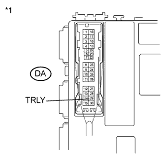
Text in Illustration *1 Component with harness connected
(Main Body ECU [Side View])
Remove the main body ECU with its connector still connected.
-
Measure the voltage according to the value(s) in the table below.
Standard Voltage Tester Connection Switch Condition Specified Condition DA-29 (TRLY) - Body Ground Light control switch
off → TAIL
Below 1 V → 11 to 14 V
NG
REPLACE MAIN BODY ECU (INSTRUMENT PANEL JUNCTION BLOCK ASSEMBLY)
OK
-
-
CHECK HARNESS AND CONNECTOR (REAR COMBINATION LIGHT [TAILLIGHT] - MAIN BODY ECU AND BODY GROUND)
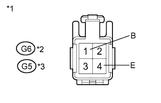
Text in Illustration *1 Front view of wire harness connector
(to Rear Combination Light)
*2 for LH *3 for RH
-
for LH:
-
Disconnect the G6 rear combination light connector.
-
Measure the voltage and resistance according to the value(s) in the table below.
Standard Voltage Tester Connection Switch Condition Specified Condition G6-1 (B) - Body ground Light control switch
TAIL
11 to 14 V Standard Resistance Tester Connection Condition Specified Condition G6-4 (E) - Body ground Always Below 1 Ω
-
-
for RH:
-
Disconnect the G5 rear combination light connector.
-
Measure the voltage and resistance according to the value(s) in the table below.
Standard Voltage Tester Connection Switch Condition Specified Condition G5-1 (B) - Body ground Light control switch
TAIL
11 to 14 V Standard Resistance Tester Connection Condition Specified Condition G5-4 (E) - Body ground Always Below 1 Ω
-
NG
REPAIR OR REPLACE HARNESS OR CONNECTOR
OK
-
-
CHECK HARNESS AND CONNECTOR (REAR LIGHT [TAILLIGHT] - MAIN BODY ECU AND BODY GROUND)
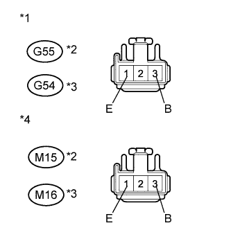
Text in Illustration *1 Front view of wire harness connector
(to Rear Light [for Sedan])
*2 for LH *3 for RH *4 Front view of wire harness connector
(to Rear Light [for Wagon])
-
for Sedan (LH Side):
-
Disconnect the G55 rear light connector.
-
Measure the voltage and resistance according to the value(s) in the table below.
Standard Voltage Tester Connection Switch Condition Specified Condition G55-3 (B) - Body ground Light control switch
TAIL
11 to 14 V Standard Resistance Tester Connection Condition Specified Condition G55-1 (E) - Body ground Always Below 1 Ω
-
-
for Sedan (RH Side):
-
Disconnect the G54 rear light connector.
-
Measure the voltage and resistance according to the value(s) in the table below.
Standard Voltage Tester Connection Switch Condition Specified Condition G54-3 (B) - Body ground Light control switch
TAIL
11 to 14 V Standard Resistance Tester Connection Condition Specified Condition G54-1 (E) - Body ground Always Below 1 Ω
-
-
for Wagon (LH Side):
-
Disconnect the M15 rear light connector.
-
Measure the voltage and resistance according to the value(s) in the table below.
Standard Voltage Tester Connection Switch Condition Specified Condition M15-3 (B) - Body ground Light control switch
TAIL
11 to 14 V Standard Resistance Tester Connection Condition Specified Condition M15-1 (E) - Body ground Always Below 1 Ω
-
-
for Wagon (RH Side):
-
Disconnect the M16 rear light connector.
-
Measure the voltage and resistance according to the value(s) in the table below.
Standard Voltage Tester Connection Switch Condition Specified Condition M16-3 (B) - Body ground Light control switch
TAIL
11 to 14 V Standard Resistance Tester Connection Condition Specified Condition M16-1 (E) - Body ground Always Below 1 Ω
-
NG
REPAIR OR REPLACE HARNESS OR CONNECTOR
OK
-
-
CHECK HARNESS AND CONNECTOR (LICENSE PLATE LIGHT - MAIN BODY ECU AND BODY GROUND)
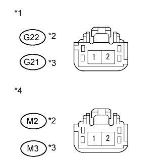
Text in Illustration *1 Front view of wire harness connector
(to License Plate Light [for Sedan])
*2 for LH *3 for RH *4 Front view of wire harness connector
(to License Plate Light [for Wagon])
-
for Sedan (LH Side):
-
Disconnect the G22 rear license plate light connector.
-
Measure the voltage and resistance according to the value(s) in the table below.
Standard Voltage Tester Connection Switch Condition Specified Condition G22-1 - Body ground Light control switch
TAIL
11 to 14 V Standard Resistance Tester Connection Condition Specified Condition G22-2 - Body ground Always Below 1 Ω
-
-
for Sedan (RH Side):
-
Disconnect the G21 rear license plate light connector.
-
Measure the voltage and resistance according to the value(s) in the table below.
Standard Voltage Tester Connection Switch Condition Specified Condition G21-1 - Body ground Light control switch
TAIL
11 to 14 V Standard Resistance Tester Connection Condition Specified Condition G21-2 - Body ground Always Below 1 Ω
-
-
for Wagon (LH Side):
-
Disconnect the M2 rear license plate light connector.
-
Measure the voltage and resistance according to the value(s) in the table below.
Standard Voltage Tester Connection Switch Condition Specified Condition M2-1 - Body ground Light control switch
TAIL
11 to 14 V Standard Resistance Tester Connection Condition Specified Condition M2-2 - Body ground Always Below 1 Ω
-
-
for Wagon (RH Side):
-
Disconnect the M3 rear license plate light connector.
-
Measure the voltage and resistance according to the value(s) in the table below.
Standard Voltage Tester Connection Switch Condition Specified Condition M3-1 - Body ground Light control switch
TAIL
11 to 14 V Standard Resistance Tester Connection Condition Specified Condition M3-2 - Body ground Always Below 1 Ω
-
NG
REPAIR OR REPLACE HARNESS OR CONNECTOR
OK
PROCEED TO NEXT SUSPECTED AREA SHOWN IN PROBLEM SYMPTOMS TABLE Click here
-