WIPER AND WASHER SYSTEM (w/ Rain Sensor) Headlight Cleaner Switch Circuit
DESCRIPTION
This circuit detects the conditions of the headlight cleaner switch.
The headlight cleaner control relay receives the following signals:
-
Headlight cleaner switch signal
-
Headlight operating signal*
-
Front washer motor operating signal*
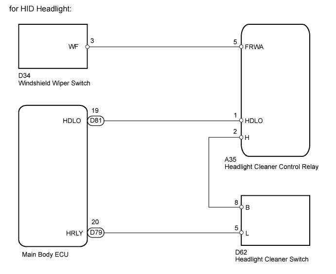
*: for HID Headlight
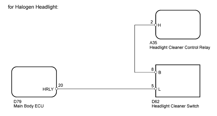
WIRING DIAGRAM
INSPECTION PROCEDURE
PROCEDURE
-
INSPECT HEADLIGHT CLEANER SWITCH ASSEMBLY
-
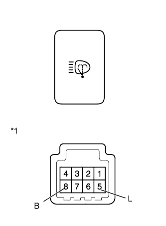
Text in Illustration *1 Component without harness connected
(Headlight Cleaner Switch)
for LHD:
Remove the headlight cleaner switch Click here.
-
for RHD:
Remove the headlight cleaner switch Click here.
-
Measure the resistance according to the value(s) in the table below.
Standard Resistance Tester Connection Switch Condition Specified Condition 8 (B) - 5 (L) Headlight cleaner switch off 10 kΩ or higher 8 (B) - 5 (L) Headlight cleaner switch on Below 1 Ω Result Result Proceed to OK A NG (for LHD) B NG (for RHD) C
B 
REPLACE HEADLIGHT CLEANER SWITCH ASSEMBLY Click here
C
REPLACE HEADLIGHT CLEANER SWITCH ASSEMBLY Click here
A 
-
-
CHECK HARNESS AND CONNECTOR (HEADLIGHT CLEANER SWITCH - HEADLIGHT CLEANER CONTROL RELAY AND MAIN BODY ECU)
-
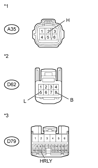
Text in Illustration *1 Front view of wire harness connector
(to Headlight Cleaner Control Relay)
*2 Front view of wire harness connector
(to Headlight Cleaner Switch)
*3 Front view of wire harness connector
(to Main Body ECU)
Disconnect the A35 relay connector.
-
Disconnect the D62 switch connector.
-
Disconnect the D79 ECU connector.
-
Measure the resistance according to the value(s) in the table below.
Standard Resistance Tester Connection Condition Specified Condition A35-2 (H) - D62-8 (B) Always Below 1 Ω D62-5 (L) - D79-20 (HRLY) A35-2 (H) - Body ground Always 10 kΩ or higher D62-8 (B) - Body ground D62-5 (L) - Body ground D79-20 (HRLY) - Body ground
NG
REPAIR OR REPLACE HARNESS OR CONNECTOR
OK
-
-
CHECK HEADLIGHT TYPE
-
Check the headlight type.
Result Result Proceed to for HID Headlight A for Halogen Headlight B
B
PROCEED TO NEXT SUSPECTED AREA SHOWN IN PROBLEM SYMPTOMS TABLE Click here
A
-
-
CHECK HARNESS AND CONNECTOR (HOLD SIGNAL)
-
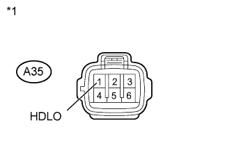
Text in Illustration *1 Front view of wire harness connector
(to Headlight Cleaner Control Relay)
Disconnect the A35 relay connector.
-
Measure the voltage according to the value(s) in the table below.
Standard Voltage Tester Connection Switch Condition Specified Condition A35-1 (HDLO) - Body ground Ignition switch ON, headlights (LO) not operating Below 1 V A35-1 (HDLO) - Body ground Ignition switch ON, headlights (LO) operating 11 to 14 V
NG 
CHECK HARNESS AND CONNECTOR (HEADLIGHT CLEANER CONTROL RELAY - MAIN BODY ECU) Click here
OK
-
-
CHECK HEADLIGHT CLEANER CONTROL RELAY (FRWA SIGNAL)
-
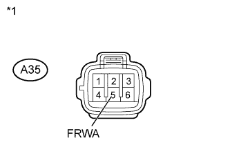
Text in Illustration *1 Front view of wire harness connector
(to Headlight Cleaner Control Relay)
Disconnect the A35 relay connector.
-
Measure the voltage according to the value(s) in the table below.
Standard Voltage Tester Connection Switch Condition Specified Condition A35-5 (FRWA) - Body ground Ignition switch ON, front washer stopped 11 to 14 V A35-5 (FRWA) - Body ground Ignition switch ON, front washer operating Below 1 V
NG
CHECK HARNESS AND CONNECTOR (HEADLIGHT CLEANER CONTROL RELAY - WINDSHIELD WIPER SWITCH) Click here
OK 
PROCEED TO NEXT SUSPECTED AREA SHOWN IN PROBLEM SYMPTOMS TABLE Click here
-
-
CHECK HARNESS AND CONNECTOR (HEADLIGHT CLEANER CONTROL RELAY - MAIN BODY ECU)
-
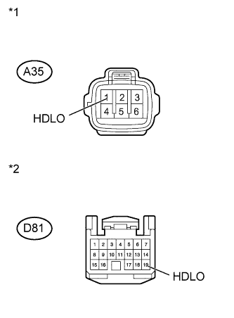
Text in Illustration *1 Front view of wire harness connector
(to Headlight Cleaner Control Relay)
*2 Front view of wire harness connector
(to Main Body ECU)
Disconnect the A35 relay connector.
-
Disconnect the D81 ECU connector.
-
Measure the resistance according to the value(s) in the table below.
Standard Resistance Tester Connection Condition Specified Condition A35-1 (HDLO) - D81-19 (HDLO) Always Below 1 Ω A35-1 (HDLO) - Body ground Always 10 kΩ or higher
NG
REPAIR OR REPLACE HARNESS OR CONNECTOR
OK
PROCEED TO NEXT SUSPECTED AREA SHOWN IN PROBLEM SYMPTOMS TABLE Click here
-
-
CHECK HARNESS AND CONNECTOR (HEADLIGHT CLEANER CONTROL RELAY - WINDSHIELD WIPER SWITCH)
-
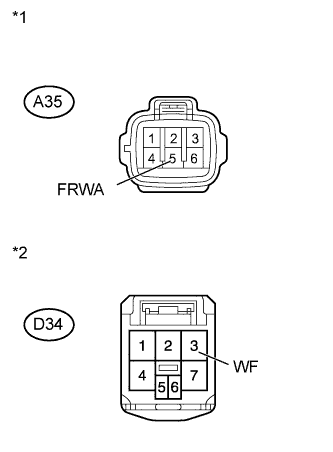
Text in Illustration *1 Front view of wire harness connector
(to Headlight Cleaner Control Relay)
*2 Front view of wire harness connector
(to Windshield Wiper Switch)
Disconnect the A35 relay connector.
-
Disconnect the D34 switch connector.
-
Measure the resistance according to the value(s) in the table below.
Standard Resistance Tester Connection Condition Specified Condition A35-5 (FRWA) - D34-3 (WF) Always Below 1 Ω A35-5 (FRWA) - Body ground Always 10 kΩ or higher
NG
REPAIR OR REPLACE HARNESS OR CONNECTOR
OK
PROCEED TO NEXT SUSPECTED AREA SHOWN IN PROBLEM SYMPTOMS TABLE Click here
-