ROOF HEADLINING (for Wagon) INSTALLATION

Tech Tips
A bolt without a torque specification is shown in the standard bolt chart Click here.
-
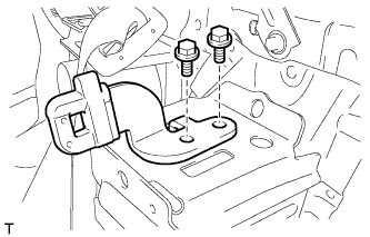
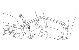
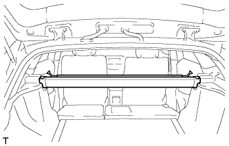
INSTALL TONNEAU COVER HOLDER BRACKET LH (w/ Partition Net)
-
Install the tonneau cover holder bracket with the 2 bolts.
-
-
INSTALL TONNEAU COVER HOLDER BRACKET RH (w/ Partition Net)
Tech Tips
Use the same procedure described for the LH side.
-
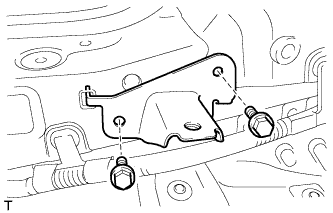
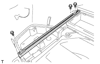
INSTALL NO. 2 DECK BOARD BRACKET
-
Install the No. 2 deck board bracket with the 2 bolts.
- Torque:
- 18 N*m { 184 kgf*cm, 13 ft.*lbf }
-
-
INSTALL NO. 1 DECK BOARD BRACKET
Tech Tips
Use the same procedure described for the No. 2 deck board bracket.
-
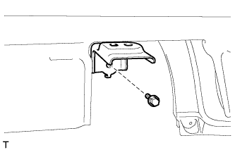
INSTALL NO. 4 LUGGAGE COMPARTMENT TRIM BRACKET (w/o Deck Rail)
-
Install the No. 4 luggage compartment trim bracket with the bolt.
- Torque:
- 7.8 N*m { 80 kgf*cm, 69 in.*lbf }
-
-
INSTALL NO. 3 LUGGAGE COMPARTMENT TRIM BRACKET (w/o Deck Rail)
Tech Tips
Use the same procedure described for the No. 4 luggage compartment trim bracket.
-
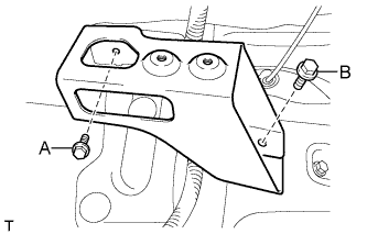
INSTALL FRONT DECK RAIL BRACKET LH (w/ Deck Rail)
-
Install the front deck rail bracket with the 2 bolts.
- Torque:
- for bolt A
- 7.8 N*m { 80 kgf*cm, 69 in.*lbf }
- for bolt B
- 42 N*m { 428 kgf*cm, 31 ft.*lbf }
-
-
INSTALL FRONT DECK RAIL BRACKET RH (w/ Deck Rail)
Tech Tips
Use the same procedure described for the LH side.
-
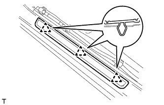
INSTALL REAR NO. 3 SIDE RAIL SPACER LH
-
Attach the 2 claws to install the No. 3 side rail spacer.
-
-
INSTALL REAR NO. 3 SIDE RAIL SPACER RH
Tech Tips
Use the same procedure described for the LH side.
-
INSTALL REAR NO. 2 SIDE RAIL SPACER LH
-
Attach the 2 claws to install the No. 2 side rail spacer.
-
-
INSTALL REAR NO. 2 SIDE RAIL SPACER RH
Tech Tips
Use the same procedure described for the LH side.
-
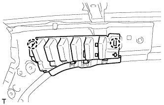
INSTALL FRONT SHOULDER BELT ANCHOR PLATE SUB-ASSEMBLY LH
-
Attach the 5 claws to install the front shoulder belt anchor plate.
-
-
INSTALL FRONT SHOULDER BELT ANCHOR PLATE SUB-ASSEMBLY RH
Tech Tips
Use the same procedure described for the LH side.
-
INSTALL REAR DOOR SCUFF PLATE OUTSIDE LH
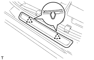
-
Attach the 2 clips to install the rear door scuff plate outside.
-
-
INSTALL REAR DOOR SCUFF PLATE OUTSIDE RH
Tech Tips
Use the same procedure described for the LH side.
-
INSTALL FRONT DOOR SCUFF PLATE OUTSIDE LH
-
Attach the 3 clips to install the front door scuff plate outside.
-
-
INSTALL FRONT DOOR SCUFF PLATE OUTSIDE RH
Tech Tips
Use the same procedure described for the LH side.
-
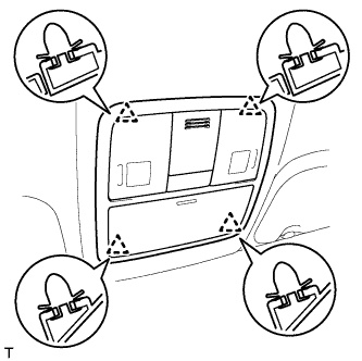
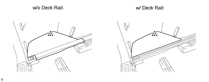
INSTALL ROOF HEADLINING ASSEMBLY
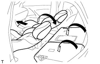
Tech Tips
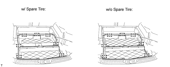
Before installing the roof headlining, move the front seats and rear seat to the positions shown in the illustration.
-
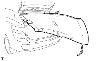
Place the roof headlining into the vehicle through the back door.
Note
Be careful not to damage the roof headlining when placing it in the cabin.
-
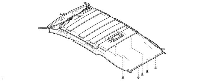
w/o Roof Sunshade System:
-
Install the roof headlining with the 5 clips.
-
-
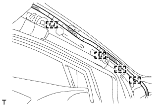
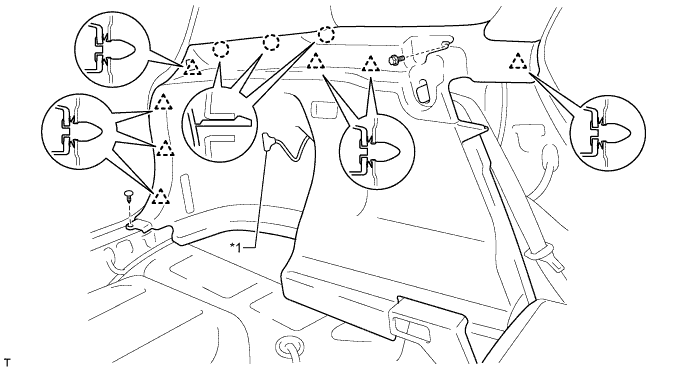
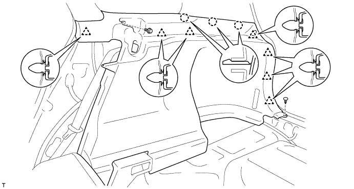
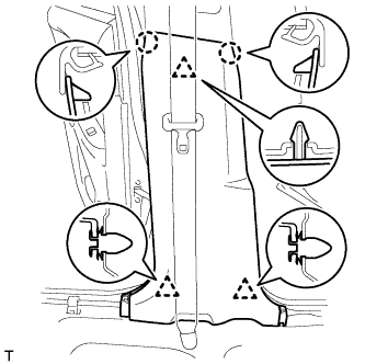
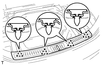
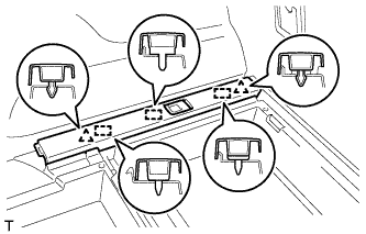
w/ Roof Sunshade System:
-
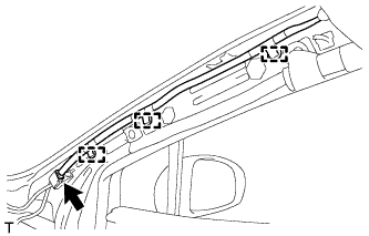
Attach the 3 guides and 12 fasteners to install the roof headlining.
-
Install the 5 clips.
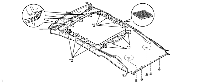
Text in Illustration *1 Guide *2 Fastener
-
-
for LHD:
-
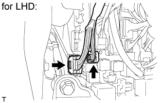
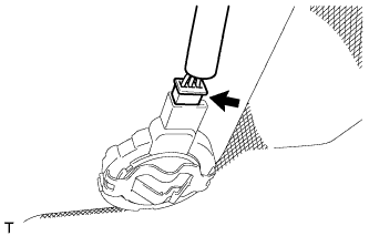
Connect the 2 roof wire connectors.
-
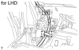
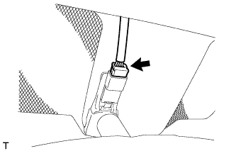
Connect the 2 clamps.
-
-
for RHD:
-
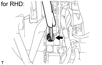
Connect the roof wire connector.
-
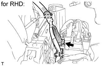
Connect the 2 clamps and connector.
-
-
Connect the 4 clamps to the front pillar LH.
-
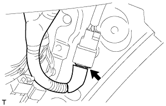
w/ Roof Sunshade System:
Connect the connector.
-
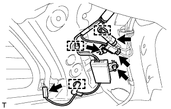
Install the antenna with the 2 bolts.
-
Connect the 3 clamps to the rear pillar RH.
-
Connect the 3 connectors.
-
Connect the 3 clamps to the front pillar RH.
-
Connect the connector.
-
w/ Rain Sensor:
Connect the rain sensor connector.
-
w/ EC Mirror:
Connect the EC mirror connector.
-
-
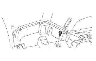
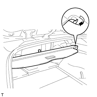
INSTALL REAR ROOM PARTITION NET HOOK LH
-
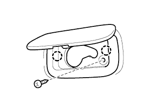
Attach the 2 claws to install the rear room partition net hook.
-
Install the screw.
-
-
INSTALL REAR ROOM PARTITION NET HOOK RH
Tech Tips
Use the same procedure described for the LH side.
-
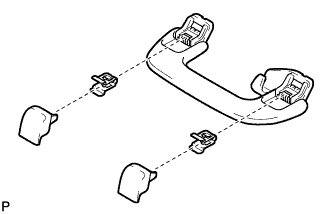
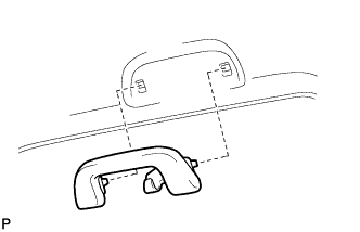
INSTALL ASSIST GRIP SUB-ASSEMBLY
Tech Tips
Use the same procedure for the other assist grip.
-
Assemble the assist grip as shown in the illustration.
-
Install the assist grip.
-
-
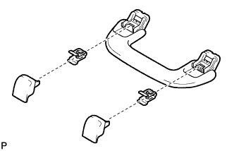
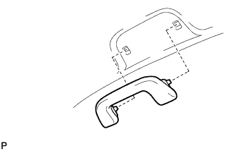
INSTALL REAR ASSIST GRIP ASSEMBLY LH
-
Assemble the rear assist grip as shown in the illustration.
-
Install the rear assist grip.
-
-
INSTALL REAR ASSIST GRIP ASSEMBLY RH
Tech Tips
Use the same procedure described for the LH side.
-
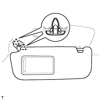
INSTALL VISOR HOLDER
Tech Tips
Use the same procedure to install the visor holder on the other side.
-
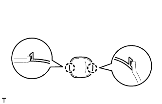
Attach the 2 claws.
-
Push in the visor holder as shown in the illustration.
-
-
INSTALL VISOR ASSEMBLY LH
-
Attach the 2 clips to install the visor.
-
-
INSTALL VISOR ASSEMBLY RH
Tech Tips
Use the same procedure described for the LH side.
-
INSTALL RAIN SENSOR COVER (w/ Rain Sensor)
-
Attach the 3 claws to install the No. 1 rain sensor cover.
-
-
INSTALL INNER REAR VIEW MIRROR STAY HOLDER COVER (w/ EC Mirror)
-
w/o Rear Monitor:
Install the inner rear view mirror stay holder cover Click here.
-
w/ Rear Monitor:
Install the inner rear view mirror stay holder cover Click here.
-
-
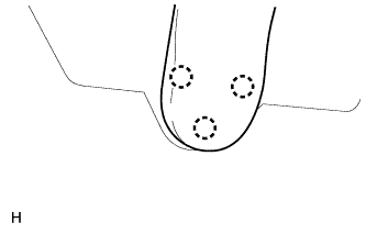
INSTALL NO. 1 ROOM LIGHT ASSEMBLY
-
Connect the connector.
-
Attach the 4 claws to install the No. 1 room light.
-
-
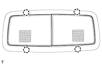
INSTALL MAP LIGHT ASSEMBLY
-
Connect the connector.
-
Attach the 4 clips to install the map light.
-
-
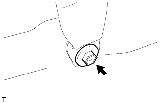
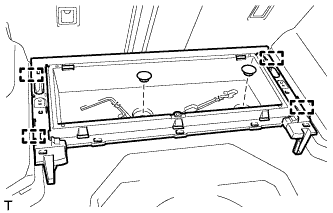
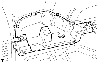
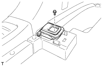
INSTALL COIN BOX ASSEMBLY
-
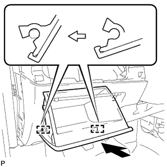
Attach the 2 hinges to install the coin box.
-
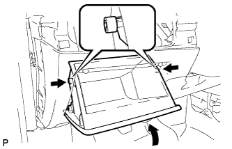
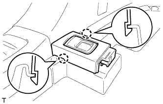
While pushing in the sides of the coin box as indicated by the arrows in the illustration, close the coin box to engage the 2 stoppers.
-
-
INSTALL UPPER INSTRUMENT PANEL SUB-ASSEMBLY
Tech Tips
-
Use the same procedure for RHD and LHD vehicles.
-
The procedure listed below is for LHD vehicles.
-
Install the upper instrument panel sub-assembly Click here.
-
-
INSTALL INNER ROOF SIDE GARNISH LH
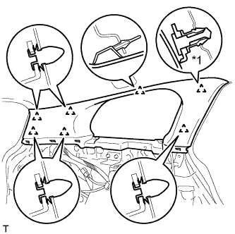
Text in Illustration *1 Clip A
-
Install a new clip A to the inner roof side garnish.
-
Attach the 7 clips to install the inner roof side garnish.
-
-
INSTALL INNER ROOF SIDE GARNISH RH
Tech Tips
Use the same procedure described for the LH side.
-
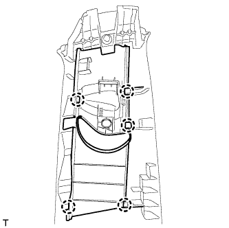
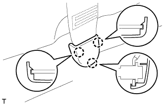
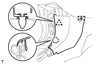
INSTALL DECK TRIM SIDE PANEL ASSEMBLY LH
-
Pass the fuel lid opener cable through the deck trim side panel.
-
Connect the connector.
-
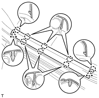
Attach the 7 clips and 3 claws to install the deck trim side panel.
-
Install the bolt and clip.
Text in Illustration *1 Fuel Lid Opener Cable - -
-
-
INSTALL DECK TRIM SIDE PANEL ASSEMBLY RH
-
Attach the 7 clips and 3 claws to install the deck trim side panel.
-
Install the bolt and clip.
-
-
INSTALL INNER ROOF SIDE GARNISH CAP LH
-
Attach the 2 claws to install the inner roof side garnish cap.
-
-
INSTALL INNER ROOF SIDE GARNISH CAP RH
Tech Tips
Use the same procedure described for the LH side.
-
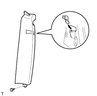
INSTALL CENTER PILLAR GARNISH LH
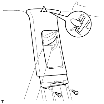
-
Pass the front seat outer belt floor anchor through the center pillar garnish.
-
Attach the clip to install the center pillar garnish.
-
Install the 2 screws.
-
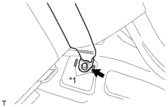
Install the front seat outer belt floor anchor with the bolt.
- Torque:
- 41 N*m { 418 kgf*cm, 30 ft.*lbf }
-
-
INSTALL CENTER PILLAR GARNISH RH
Tech Tips
Use the same procedure described for the LH side.
-
INSTALL LAP BELT OUTER ANCHOR COVER
Tech Tips
Use the same procedure for the other lap belt outer anchor cover.
-
Attach the 3 claws to install the lap belt outer anchor cover.
-
-
INSTALL LOWER CENTER PILLAR GARNISH LH
-
Attach the 2 claws and 3 clips to install the lower center pillar garnish.
-
-
INSTALL LOWER CENTER PILLAR GARNISH RH
Tech Tips
Use the same procedure described for the LH side.
-
INSTALL FRONT PILLAR GARNISH LH
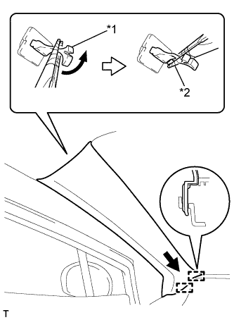
Text in Illustration *1 Front Pillar Garnish Clip *2 Protective Tape
-
Remove the protective cover.
-
Attach the 2 guides.
-
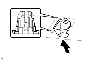
Turn the end of the front pillar garnish clip 90° with needle-nose pliers and install it to the front pillar garnish.
Tech Tips
Tape the tips of the needle-nose pliers before use.
-
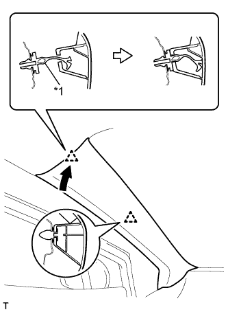
Text in Illustration *1 Front Pillar Garnish Clip Attach the 2 clips to install the front pillar garnish.
-
-
INSTALL FRONT PILLAR GARNISH RH
Tech Tips
Use the same procedure described for the LH side.
-
INSTALL BACK DOOR WEATHERSTRIP
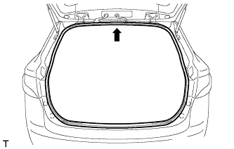
-
Align the center mark of the back door weatherstrip with the position indicated by the arrow in the illustration and install the back door weatherstrip.
-
-
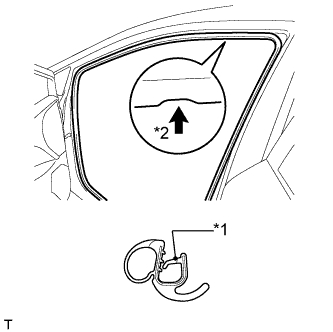
INSTALL REAR DOOR OPENING TRIM WEATHERSTRIP LH
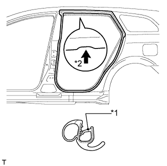
Text in Illustration *1 Paint Mark *2 Mark Position
-
Install the rear door opening trim weatherstrip as shown in the illustration.
-
-
INSTALL REAR DOOR OPENING TRIM WEATHERSTRIP RH
Tech Tips
Use the same procedure described for the LH side.
-
INSTALL REAR DOOR SCUFF PLATE LH
-
Attach the clip and 6 claws to install the front door scuff plate.
-
-
INSTALL REAR DOOR SCUFF PLATE RH
Tech Tips
Use the same procedure described for the LH side.
-
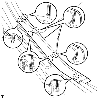
INSTALL FRONT DOOR OPENING TRIM WEATHERSTRIP LH
Text in Illustration *1 Paint Mark *2 Mark Position
-
Install the front door opening trim weatherstrip as shown in the illustration.
-
-
INSTALL FRONT DOOR OPENING TRIM WEATHERSTRIP RH
Tech Tips
Use the same procedure described for the LH side.
-
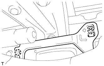
INSTALL COWL SIDE TRIM BOARD LH
-
Attach the clip, claw and guide to install the cowl side trim board.
-
-
INSTALL COWL SIDE TRIM BOARD RH
Tech Tips
Use the same procedure described for the LH side.
-
INSTALL FRONT DOOR SCUFF PLATE LH
-
Attach the 2 clips and 8 claws to install the front door scuff plate.
-
-
INSTALL FRONT DOOR SCUFF PLATE RH
Tech Tips
Use the same procedure described for the LH side.
-
INSTALL FRONT DECK FLOOR BOX
-
Attach the 4 guides to install the front deck floor box.
-
Install the 2 clips.
-
-
INSTALL REAR FLOOR FINISH PLATE
-
Attach the 4 clips to install the rear floor finish plate.
-
-
INSTALL DECK FLOOR BOX LH
-
Attach the 5 guides to install the deck floor box.
-
-
INSTALL DECK FLOOR BOX RH
Tech Tips
Use the same procedure described for the LH side.
-
INSTALL ROPE HOOK ASSEMBLY (w/o Deck Rail)
Tech Tips
Use the same procedure for all the rope hooks.
-
Install the rope hook with the bolt.
- Torque:
- 18 N*m { 184 kgf*cm, 13 ft.*lbf }
-
-
INSTALL NO. 6 DECK SIDE TRIM COVER (w/o Deck Rail)
-
Attach the 2 claws to install the No. 6 deck side trim cover.
-
-
INSTALL NO. 5 DECK SIDE TRIM COVER (w/o Deck Rail)
Tech Tips
Use the same procedure described for the No. 6 deck side trim cover.
-
INSTALL NO. 2 DECK SIDE TRIM COVER (w/o Deck Rail)
-
Attach the 2 clips and 3 guides to install the No. 2 deck side trim cover.
-
-
INSTALL NO. 1 DECK SIDE TRIM COVER (w/o Deck Rail)
Tech Tips
Use the same procedure described for the No. 2 deck side trim cover.
-
INSTALL FLOOR SIDE RAIL LH (w/ Deck Rail)
-
Install the floor side rail with the 3 bolts.
- Torque:
- 18 N*m { 184 kgf*cm, 13 ft.*lbf }
-
-
INSTALL FLOOR SIDE RAIL RH (w/ Deck Rail)
Tech Tips
Use the same procedure described for the LH side.
-
INSTALL REAR DECK FLOOR BOX
-
Attach the 7 guides to install the rear deck floor box.
-
Install the bolt.
-
Install the bolt.
-
-
INSTALL NO. 3 DECK BOARD SUB-ASSEMBLY
-
Attach the clip to install the No. 3 deck board.
-
-
INSTALL NO. 2 DECK BOARD SUB-ASSEMBLY
Tech Tips
Use the same procedure described for the No. 3 deck board.
-
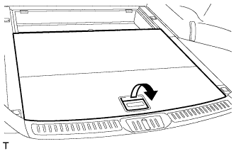
INSTALL DECK BOARD SUB-ASSEMBLY
-
Pull the lever to install the deck board.
-
-
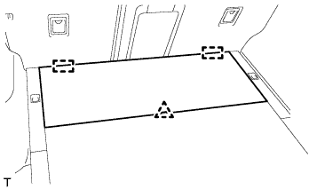
INSTALL DECK BOARD ASSEMBLY
-
Attach the clip and 2 guides to install the deck board.
-
-
INSTALL LOWER DECK TRIM SIDE BOARD LH (w/ Partition Board)
-
Install the lower deck trim side board.
-
-
INSTALL LOWER DECK TRIM SIDE BOARD RH (w/ Partition Board)
-
Install the lower deck trim side board.
-
-
INSTALL ROOM PARTITION NET ASSEMBLY (w/ Partition Net)
-
Install the room partition net.
-
-
INSTALL TONNEAU COVER ASSEMBLY (w/ Tonneau Cover)
-
Pull the lever to install the tonneau cover.
-
-
INSTALL REAR SIDE SEATBACK ASSEMBLY LH
-
Install the claw as shown in the illustration.
-
Install the side seatback with the bolt.
- Torque:
- 7.8 N*m { 80 kgf*cm, 69 in.*lbf }
-
Text in Illustration *1 Protruding Part Install the rear seat 3 point type belt anchor with the bolt.
- Torque:
- 41 N*m { 418 kgf*cm, 30 ft.*lbf }
Note
Do not allow the anchor part of the rear seat 3 point type belt to overlap the protruding parts of the floor panel.
-
Install the seat belt to the belt guide.
-
Attach the claw to close the cap of the rear seat shoulder belt guide.
-
Check if the ELR locks.
Note
The check should be performed with the outer belt assembly installed.
-
With the belt assembly installed, check that the belt locks when it is pulled out quickly.
-
-
-
INSTALL REAR SIDE SEATBACK ASSEMBLY RH
Tech Tips
Use the same procedure described for the LH side.
-
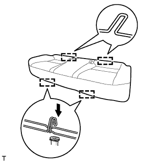
INSTALL BENCH TYPE REAR SEAT CUSHION ASSEMBLY
-
Attach the 2 rear hooks of the seat cushion to the seatback.
-
Attach the 2 front hooks to install the seat cushion.
-
Confirm that the seat cushion is firmly installed.
Note
When installing the seat cushion, make sure the seat belt buckle is not under the seat cushion.
-
-
CONNECT CABLE TO NEGATIVE BATTERY TERMINAL
Note
When disconnecting the cable, some systems need to be initialized after the cable is reconnected Click here.