LOWER INSTRUMENT PANEL INSTALLATION

Tech Tips
-
Use the same procedure for RHD and LHD vehicles.
-
The procedure listed below is for LHD vehicles.
-
A bolt without a torque specification is shown in the standard bolt chart Click here.
-
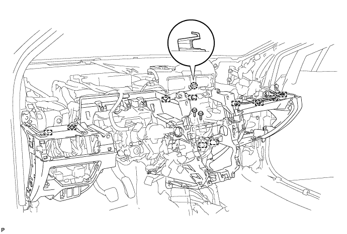
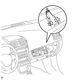
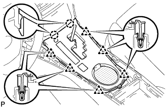
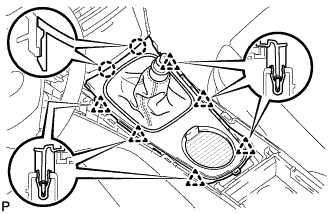
INSTALL LOWER INSTRUMENT PANEL SUB-ASSEMBLY
-
Attach the claw to install the instrument panel.
-
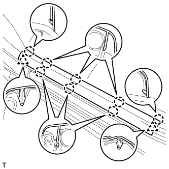
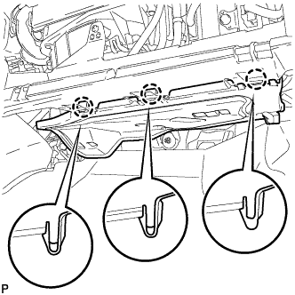
Attach the 10 clamps.
-
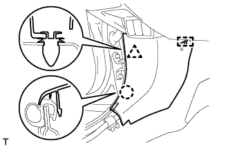
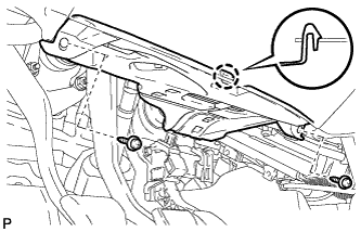
Install the 2 bolts.
-
Install the screw.
-
Install the screw <D>.
-
Install the 2 bolts <B> and 8 screws <C>.
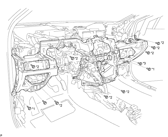
Text in Illustration *1 Bolt <B> *3 Screw <D> *2 Screw <C> - - -
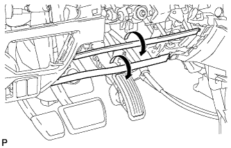
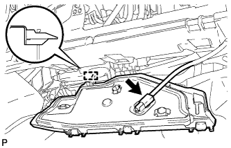
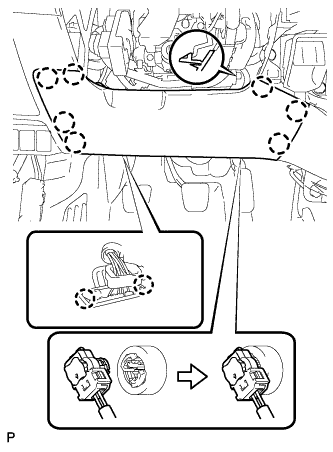
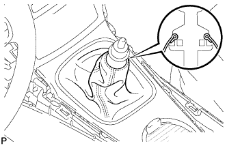
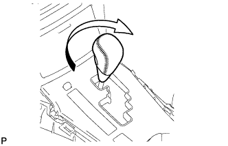
When replacing the lower instrument panel sub-assembly with a new one:
-
Twist the ribs (the pieces used to maintain the shape of the panel) in the direction of the arrow in the illustration until it detaches from the instrument panel, and remove the rib.
-
-
-
INSTALL COOLER (ROOM TEMPERATURE SENSOR) THERMISTOR (for Automatic Air Conditioning System)
-
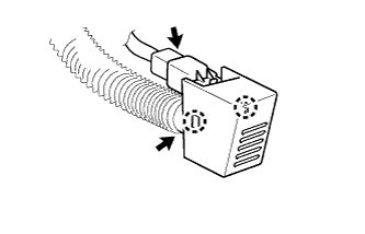
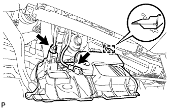
Attach the 2 claws to install the thermistor.
-
Connect the connector and aspirator hose.
-
-
INSTALL HOOD LOCK CONTROL LEVER SUB-ASSEMBLY
-
Connect the hood lock control cable assembly.
-
Attach the 3 claws to install the hood lock control lever sub-assembly.
-
-
INSTALL FUEL LID OPENER SWITCH
-
Attach the 2 claws to install the fuel lid opener switch.
-
Connect the connector.
-
-
INSTALL VSC OFF SWITCH (w/ VSC)
-
Attach the 2 claws to install the VSC OFF switch to the lower instrument panel.
-
Connect the VSC OFF switch connector.
-
-
INSTALL HEADLIGHT SWIVEL MAIN SWITCH (w/ AFS)
-
Connect the connector.
-
Attach the 2 claws to install the switch.
-
-
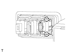
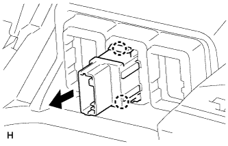
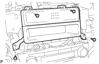
INSTALL CLEARANCE WARNING ECU ASSEMBLY (w/ TOYOTA Parking Assist-sensor System)
-
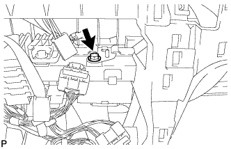
Install the ECU with the bolt.
-
Connect the connector.
-
-
INSTALL ENGINE SWITCH (for LHD with Entry and Start System)
-
Connect the connector.
-
Attach the 2 claws to install the switch.
-
-
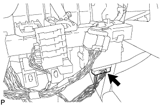
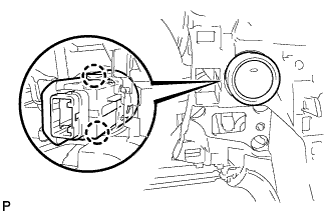
INSTALL ELECTRIC PARKING BRAKE SWITCH ASSEMBLY
-
Connect the connector.
-
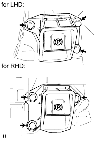
Install the electric parking brake switch with the 3 bolts.
- Torque:
- 7.1 N*m { 72 kgf*cm, 62 in.*lbf }
-
-
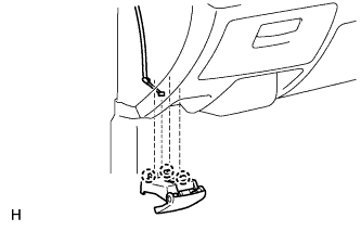
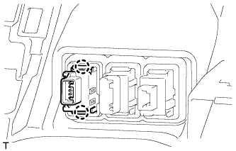
INSTALL GLOVE BOX LIGHT ASSEMBLY
-
Connect the connector.
-
Attach the 2 claws to install the glove box light.
-
-
INSTALL COWL SIDE TRIM BOARD LH
-
Attach the clip, claw and guide to install the cowl side trim board.
-
-
INSTALL COWL SIDE TRIM BOARD RH
Tech Tips
Use the same procedure described for the LH side.
-
INSTALL FRONT DOOR SCUFF PLATE LH
-
Attach the 2 clips and 8 claws to install the front door scuff plate.
-
-
INSTALL FRONT DOOR SCUFF PLATE RH
Tech Tips
Use the same procedure described for the LH side.
-
INSTALL NO. 2 INSTRUMENT PANEL UNDER COVER SUB-ASSEMBLY
-
Attach the guide.
-
Connect the connector.
-
Attach the 3 claws to install the under cover.
-
-
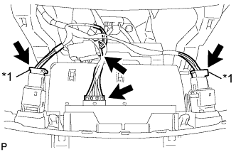
INSTALL LOWER NO. 1 INSTRUMENT PANEL AIRBAG ASSEMBLY
-
Connect the connector.
Note
When handling the airbag connector, take care not to damage the airbag wire harness.
-
Attach the 2 claws to install the DLC3.
-
Attach the 7 claws to install the instrument panel airbag.
-
Install the 4 bolts.
- Torque:
- 10 N*m { 102 kgf*cm, 7 ft.*lbf }
-
-
INSTALL NO. 1 INSTRUMENT PANEL UNDER COVER SUB-ASSEMBLY
-
Attach the guide.
-
Connect the connectors.
-
Attach the claw to install the under cover.
-
Install the 2 screws <A>.
-
-
INSTALL COIN BOX ASSEMBLY
-
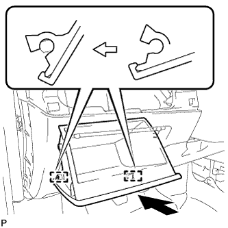
Attach the 2 hinges to install the coin box.
-
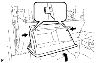
While pushing in the sides of the coin box as indicated by the arrows in the illustration, close the coin box to engage the 2 stoppers.
-
-
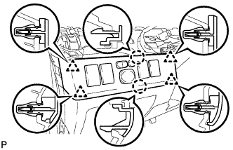
INSTALL NO. 1 SWITCH HOLE BASE (for RHD)
-
Connect the connectors.
-
Attach the 3 claws and 4 clips to install the switch hole base.
-
-
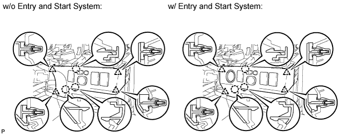
INSTALL NO. 1 SWITCH HOLE BASE (for LHD)
-
Connect the connectors.
-
Attach the 2 claws and 4 clips to install the switch hole base.
-
-
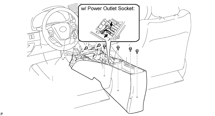
INSTALL CONSOLE BOX ASSEMBLY (w/o Console Box Lid)
-
Install the console box with the 2 screws.
-
w/ Power Outlet Socket:
-
Connect the connectors.
-
-
Install the 4 bolts.
-
-
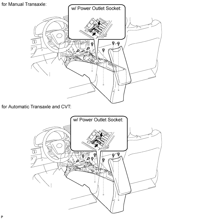
INSTALL CONSOLE BOX ASSEMBLY (w/ Console Box Lid)
-
for Manual Transaxle:
-
Install the console box with the 2 screws.
-
-
for Automatic Transaxle and CVT:
-
Install the console box with the 4 screws.
-
-
w/ Power Outlet Socket:
-
Connect the connectors.
-
-
Install the 4 bolts.
-
-
INSTALL CONSOLE BOX CARPET (w/o Console Box Lid)
-
Install the 3 carpets.
-
-
INSTALL CONSOLE BOX CARPET (w/ Console Box Lid)
-
Install the 2 carpets.
-
-
INSTALL REAR CONSOLE BOX CUP HOLDER (w/ Console Box Lid)
-
Install the cup holder.
-
-
INSTALL LOWER INSTRUMENT CLUSTER FINISH PANEL
-
Text in Illustration *1 w/ Seat Heater System Connect the connectors.
-
Attach the 2 clips to install the finish panel.
-
-
INSTALL REAR UPPER CONSOLE PANEL SUB-ASSEMBLY (for Automatic Transaxle and CVT)
-
Connect the connector.
-
Attach the 2 claws and 6 clips to install the console panel.
-
-
INSTALL REAR UPPER CONSOLE PANEL SUB-ASSEMBLY (for Manual Transaxle)
-
Attach the 2 claws and 6 clips to install the console panel.
-
Attach the cover to the shaft.
-
-
INSTALL SHIFT LEVER KNOB SUB-ASSEMBLY (for Automatic Transaxle and CVT)
-
Install the shift lever knob and twist it in the direction indicated by the arrow.
-
-
INSTALL SHIFT LEVER KNOB SUB-ASSEMBLY (for Manual Transaxle)
-
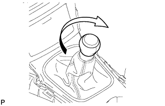
Install the shift lever knob and twist it in the direction indicated by the arrow.
-
-
INSTALL LOWER INSTRUMENT CLUSTER FINISH PANEL
-
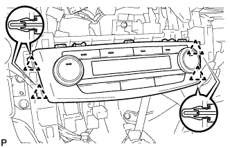
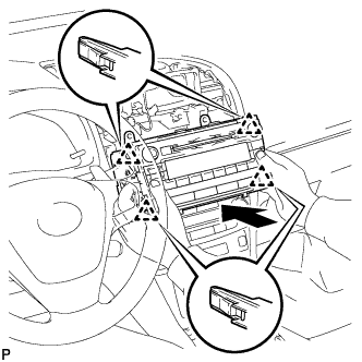
INSTALL AIR CONDITIONING CONTROL ASSEMBLY
-
Connect the connector.
-
Attach the 4 clips to install the air conditioning control.
-
-
INSTALL NAVIGATION RECEIVER ASSEMBLY WITH BRACKET (w/ Navigation System for HDD)
-
Connect the connectors.
-
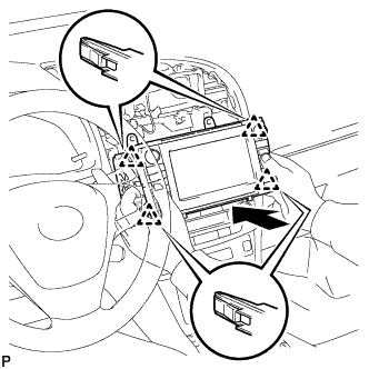
Insert the display to attach the 4 clips on its backside.
Note
When inserting the navigation receiver, do not press the knobs on the navigation receiver.
-
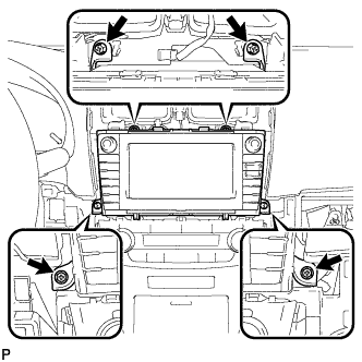
Install the navigation receiver with the 4 screws.
- Torque:
- 4.0 N*m { 40 kgf*cm, 35 in.*lbf }
-
-
INSTALL NAVIGATION RECEIVER ASSEMBLY WITH BRACKET (w/ Navigation System for DVD)
-
Connect the connectors.
-
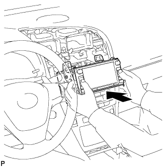
Insert the navigation receiver.
Note
When inserting the navigation receiver, do not press the knobs on the navigation receiver.
-
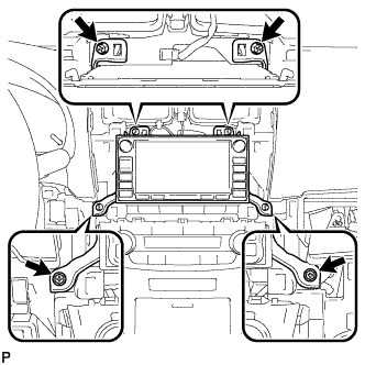
Install the navigation receiver with the 4 screws.
- Torque:
- 4.0 N*m { 40 kgf*cm, 35 in.*lbf }
-
-
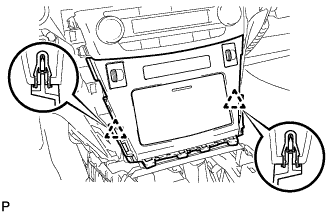
INSTALL RADIO RECEIVER WITH BRACKET (w/ Audio)
-
Connect the connectors.
-
Insert the radio receiver to attach the 4 clips on its backside.
Note
When inserting the radio receiver, do not press the knobs on it.
-
Install the radio receiver with the 4 screws.
- Torque:
- 4.0 N*m { 40 kgf*cm, 35 in.*lbf }
-
-
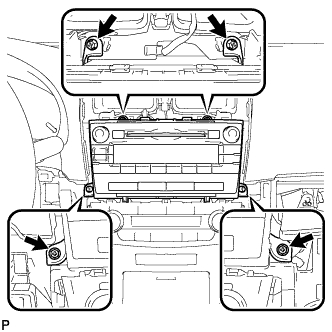
INSTALL STEREO OPENING COVER WITH BRACKET (w/o Audio)
-
Install the opening cover with bracket with the 4 screws.
-
-
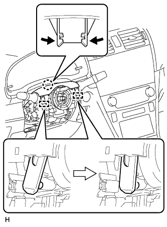
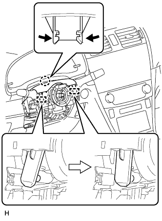
INSTALL COMBINATION SWITCH ASSEMBLY WITH SPIRAL CABLE SUB-ASSEMBLY
-
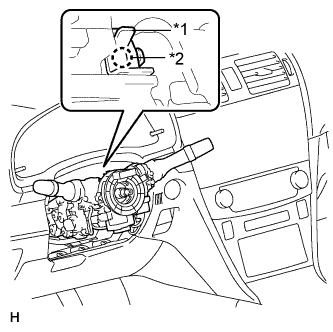
Text in Illustration *1 Clamp *2 Claw Using pliers, pinch the clamp and attach the claw to install the combination switch assembly with spiral cable sub-assembly to the steering column assembly.
-
Connect the connectors to the combination switch assembly with spiral cable sub-assembly.
-
-
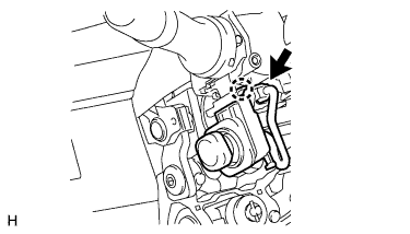
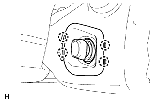
INSTALL TILT AND TELESCOPIC SWITCH (for Power Tilt and Power Telescopic Steering Column)
-
Attach the claw to install the switch.
-
Connect the switch connector.
-
-
INSTALL LOWER STEERING COLUMN COVER (for Power Tilt and Power Telescopic Steering Column)
Note
If the steering column cover is installed in an incorrect order, it will not be possible to assemble the steering column cover.
-
Attach the claw and 2 pins to install the upper steering column cover.
-
-
INSTALL UPPER STEERING COLUMN COVER (for Power Tilt and Power Telescopic Steering Column)
Note
If the steering column cover is installed in an incorrect order, it will not be possible to assemble the steering column cover.
-
Attach the claw and 2 pins to install the upper steering column cover.
-
-
INSTALL LOWER NO. 2 STEERING COLUMN COVER (for Power Tilt and Power Telescopic Steering Column)
-
Attach the 4 claws to install the lower No. 2 steering column cover.
-
-
INSTALL LOWER STEERING COLUMN COVER (for Manual Tilt and Manual Telescopic Steering Column)
Note
If the steering column cover is installed in an incorrect order, it will not be possible to assemble the steering column cover.
-
Attach the claw and 2 pins to install the upper steering column cover.
-
-
INSTALL UPPER STEERING COLUMN COVER (for Manual Tilt and Manual Telescopic Steering Column)
Note
If the steering column cover is installed in an incorrect order, it will not be possible to assemble the steering column cover.
-
Attach the claw and 2 pins to install the upper steering column cover.
-
-
INSTALL STEERING WHEEL ASSEMBLY
-
Install the steering wheel assembly Click here.
-
-
INSTALL UPPER INSTRUMENT PANEL SUB-ASSEMBLY
-
Install the upper instrument panel sub-assembly Click here.
-
-
CONNECT CABLE TO NEGATIVE BATTERY TERMINAL
Note
When disconnecting the cable, some systems need to be initialized after the cable is reconnected Click here.
-
RESTORE AUTOAWAY/RETURN FUNCTION (for Power Tilt and Power Telescopic Steering Column)
-
Restore the Autoaway/Return function setting to the previous condition by changing the customize parameter Click here.
-
-
CHECK SRS WARNING LIGHT
-
Check the SRS warning light Click here.
-