UPPER INSTRUMENT PANEL REMOVAL

Tech Tips
-
Use the same procedure for RHD and LHD vehicles.
-
The procedure listed below is for LHD vehicles.
-
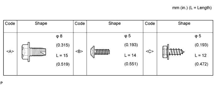
TABLE OF BOLT, SCREW AND NUT
Tech Tips
All bolts, screws and nuts relevant to installing and removing the instrument panel are shown along with their alphabet code in the table below.
-
DISABLE AUTOAWAY/RETURN FUNCTION (for Power Tilt and Power Telescopic Steering Column)
-
Disable the Autoaway/Return function by changing the customize parameter Click here.
Note
Record the current customize parameter setting (whether the Autoaway/Return function is enabled or disabled) in order to restore the current setting after finishing the operation.
Tech Tips
Performing the above operation causes the Autoaway/Return function to be disabled when the ignition switch is turned off.
-
Turn the ignition switch to ON. Operate the tilt and telescopic switch to fully extend and lower the steering column.
-
Turn the ignition switch off.
-
-
DISCONNECT CABLE FROM NEGATIVE BATTERY TERMINAL
CAUTION:
Wait at least 90 seconds after disconnecting the cable from the negative (-) battery terminal to disable the SRS system.
Note
-
w/ Navigation System for HDD:
After the ignition switch is turned off, the HDD navigation system requires approximately a minute to record various types of memory and settings. As a result, after turning the ignition switch off, wait a minute or more before disconnecting the cable from the negative (-) battery terminal.
-
When disconnecting the cable, some systems need to be initialized after the cable is reconnected Click here.
-
-
REMOVE COMBINATION METER ASSEMBLY
-
Remove the combination meter assembly Click here.
-
-
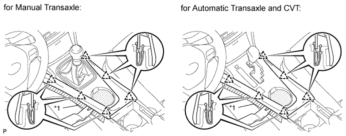
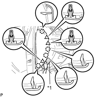
REMOVE LOWER NO. 2 INSTRUMENT PANEL FINISH PANEL
-
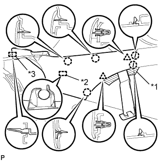
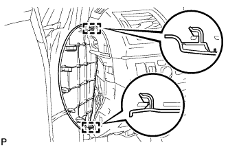
Text in Illustration *1 Protective Tape *2 Clamp *3 Guide Place protective tape as shown in the illustration.
-
Using a moulding remover B, detach the 2 clips and 5 claws.
-
Detach the clamp.
-
Detach the guide near the front of the vehicle and remove the finish panel.
-
-
REMOVE LOWER NO. 1 INSTRUMENT PANEL FINISH PANEL
-
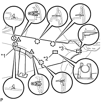
Text in Illustration *1 Protective Tape *2 Clamp *3 Guide Place protective tape as shown in the illustration.
-
Using a moulding remover B, detach the 2 clips and 5 claws.
-
Detach the clamp.
-
Detach the guide near the front of the vehicle and remove the finish panel.
-
-
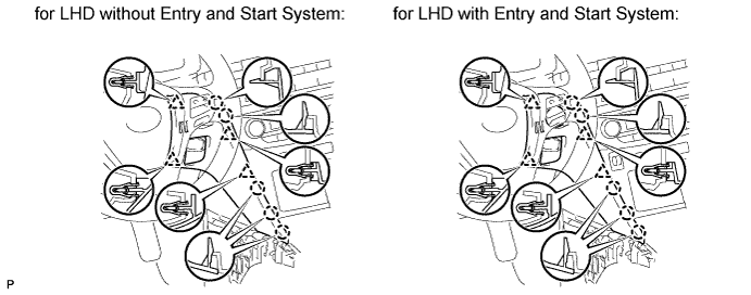
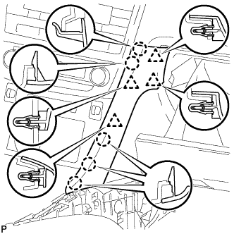
REMOVE NO. 3 BOX PANEL (w/o Console Box Lid)
-
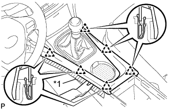
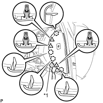
Text in Illustration *1 Protective Tape Place protective tape as shown in the illustration.
-
Using a moulding remover B, detach the 6 clips and remove the box panel.
-
-
REMOVE NO. 3 BOX PANEL (w/ Console Box Lid)
-
Place protective tape as shown in the illustration.
-
Using a moulding remover, detach the 6 clips and remove the box panel.
Text in Illustration *1 Protective Tape
-
-
REMOVE INSTRUMENT PANEL FINISH PANEL END LH
-
Using a moulding remover B, detach the 4 clips and 5 claws and remove the panel end.
-
-
REMOVE INSTRUMENT PANEL FINISH PANEL END RH (for LHD)
-
Using a moulding remover B, detach the 4 clips and 5 claws and remove the panel end.
-
-
REMOVE GLOVE COMPARTMENT DOOR ASSEMBLY
-
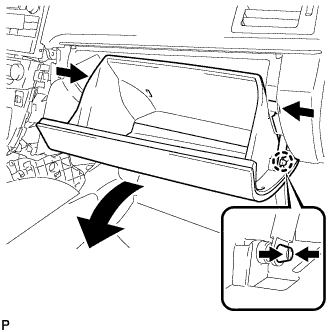
Slightly bend the upper part of the glove compartment door to release the 2 stoppers and open the glove compartment door until it is horizontal.
-
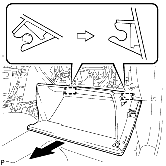
Pull the glove compartment door toward the rear of the vehicle to detach the 2 hinges and remove the glove compartment door.
-
-
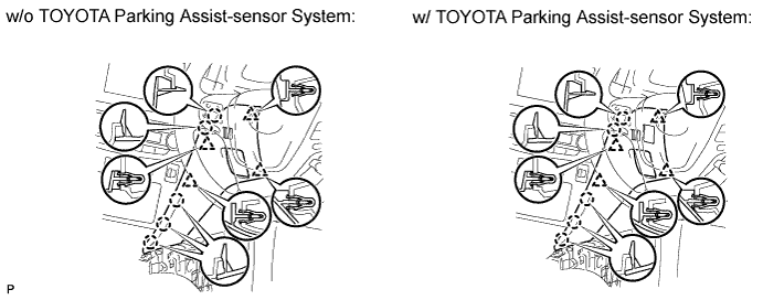
REMOVE INSTRUMENT PANEL FINISH PANEL END RH (for RHD)
-
w/o TOYOTA Parking Assist-sensor System:
-
Using a moulding remover B, detach the 4 clips and 5 claws and remove the panel end.
-
-
w/ TOYOTA Parking Assist-sensor System:
-
Using a moulding remover B, detach the 4 clips and 5 claws.
-
Remove the panel end and then disconnect the connector.
-
-
-
REMOVE CENTER INSTRUMENT PANEL REGISTER ASSEMBLY WITH FINISH PANEL (for Audio-less, DVD Navigation System)
-
Text in Illustration *1 Protective Tape Place protective tape as shown in the illustration.
-
Using a moulding remover B, detach the 2 clips and hook.
-
Detach the 3 claws and 3 hooks.
-
Detach the 6 clips.
-
Remove the panel register. Then disconnect the connector and detach the clamp.
-
-
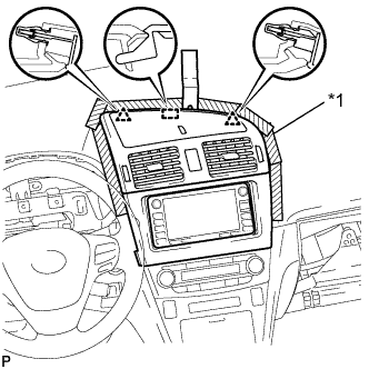
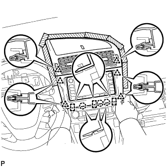
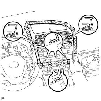
REMOVE CENTER INSTRUMENT PANEL REGISTER ASSEMBLY WITH FINISH PANEL (for Audio, HDD Navigation System)
-
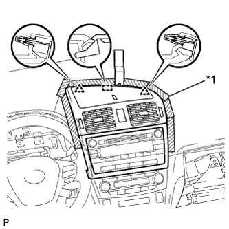
Text in Illustration *1 Protective Tape Place protective tape as shown in the illustration.
-
Using a moulding remover B, detach the 2 clips and hook.
-
Detach the 3 claws and 3 hooks.
-
Detach the 2 clips.
-
Remove the panel register. Then disconnect the connector and detach the clamp.
-
-
REMOVE INSTRUMENT SIDE PANEL LH
-
Text in Illustration *1 Protective Tape Place protective tape as shown in the illustration.
-
Using a moulding remover B, detach the 3 clips and 4 claws.
-
Detach the 2 hooks and remove the side panel.
-
-
REMOVE INSTRUMENT SIDE PANEL RH
-
Text in Illustration *1 Protective Tape Place protective tape as shown in the illustration.
-
Using a moulding remover B, detach the 3 clips and 4 claws.
-
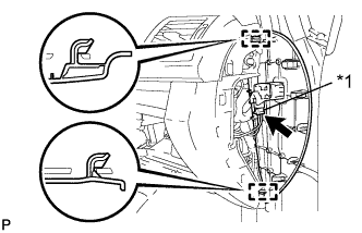
Text in Illustration *1 w/ Airbag Cut Off Switch Cylinder w/ Airbag Cut Off Switch Cylinder:
-
Disconnect the connector.
-
-
Detach the 2 hooks and remove the side panel.
-
-
REMOVE FRONT PILLAR GARNISH LH (for Sedan)
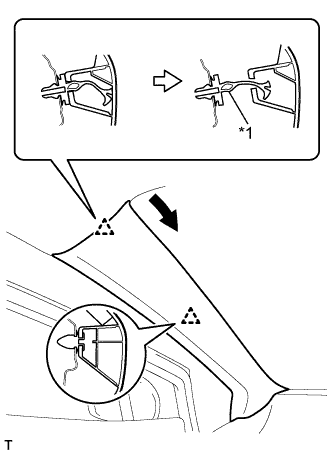
Text in Illustration *1 Front Pillar Garnish Clip
-
Pull the upper part of the garnish toward the inside of the cabin and detach the 2 clips.
Tech Tips
Make the front pillar garnish hang down from the front pillar garnish clip.
-
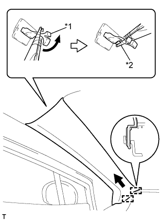
Text in Illustration *1 Front Pillar Garnish Clip *2 Protective Tape Turn the end of the front pillar garnish clip 90° with needle-nosed pliers and remove it from the front pillar garnish.
Note
-
Front pillar garnish clips are reusable if they are not removed from the vehicle and have no damage.
-
Replace the front pillar garnish clips with new ones if they are removed from the vehicle.
Tech Tips
Tape the needle-nosed pliers tip before use.
-
-
Detach the 2 guides and remove the front pillar garnish.
-
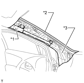
Text in Illustration *1 Curtain Shield Airbag Assembly *2 Adhesive Tape *3 Protective Cover w/ Curtain Shield Airbag:
Protect the curtain shield airbag assembly.
-
Completely cover the airbag with a cloth or nylon sheet and secure the ends of the cover with adhesive tape as shown in the illustration.
Note
Cover the curtain shield airbag with a protective cover as soon as the front pillar garnish is removed.
-
-
-
REMOVE FRONT PILLAR GARNISH LH (for Wagon)
Text in Illustration *1 Front Pillar Garnish Clip
-
Pull the upper part of the garnish toward the inside of the cabin and detach the 2 clips.
Tech Tips
Make the front pillar garnish hang down from the front pillar garnish clip.
-
Text in Illustration *1 Front Pillar Garnish Clip *2 Protective Tape Turn the end of the front pillar garnish clip 90° with needle-nosed pliers and remove it from the front pillar garnish.
Note
-
Front pillar garnish clips are reusable if they are not removed from the vehicle and have no damage.
-
Replace the front pillar garnish clips with new ones if they are removed from the vehicle.
Tech Tips
Tape the needle-nosed pliers tip before use.
-
-
Detach the 2 guides and remove the front pillar garnish.
-
Text in Illustration *1 Curtain Shield Airbag Assembly *2 Adhesive Tape *3 Protective Cover Protect the curtain shield airbag assembly.
-
Completely cover the airbag with a cloth or nylon sheet and secure the ends of the cover with adhesive tape as shown in the illustration.
Note
Cover the curtain shield airbag with a protective cover as soon as the front pillar garnish is removed.
-
-
-
REMOVE FRONT PILLAR GARNISH RH (for Sedan)
Tech Tips
Use the same procedure described for the LH side.
-
REMOVE FRONT PILLAR GARNISH RH (for Wagon)
Tech Tips
Use the same procedure described for the LH side.
-
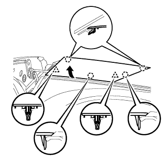
REMOVE NO. 2 INSTRUMENT PANEL SPEAKER PANEL SUB-ASSEMBLY
-
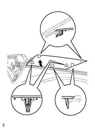
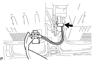
Detach the claws and clips shown in the illustration on the bottom of the panel. Then, using the 2 claws on the side of the panel towards the front of the vehicle as pivot points, lift up the panel in the direction indicated by the arrow in the illustration until the speaker connector can be disconnected.
-
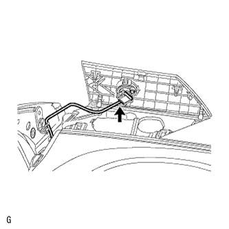
Disconnect the connector and remove the panel together with the speaker.
-
-
REMOVE NO. 2 INSTRUMENT PANEL SPEAKER PANEL SUB-ASSEMBLY (for 11 Speakers)
-
Detach the 2 clips and 4 claws and remove the speaker panel.
-
-
REMOVE NO. 1 INSTRUMENT PANEL SPEAKER PANEL SUB-ASSEMBLY
Tech Tips
Use the same procedure described for the No. 2 instrument panel speaker panel.
-
REMOVE NO. 1 INSTRUMENT PANEL SPEAKER PANEL SUB-ASSEMBLY (for 11 Speakers)
Tech Tips
Use the same procedure described for the No. 2 instrument panel speaker panel.
-
REMOVE UPPER INSTRUMENT PANEL SUB-ASSEMBLY
-
Remove the passenger airbag bolt <A>.
-
Disconnect the connectors and clamps.
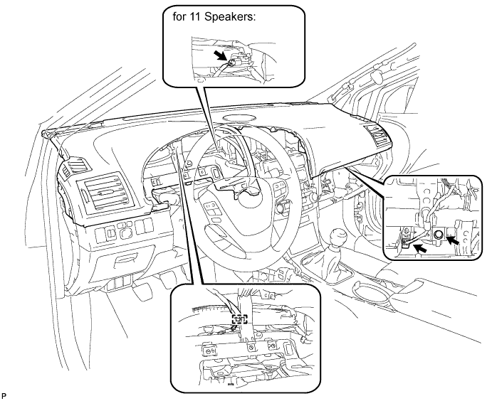
-
Remove the 3 screws <B>.
-
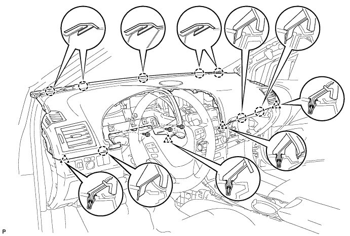
Pull up the instrument panel to detach the 8 claws and 4 clips and remove the instrument panel.
Note
Be careful not to damage the steering wheel.
-
-
REMOVE GLOVE COMPARTMENT DOOR LOCK CYLINDER ASSEMBLY (w/ Key Cylinder)
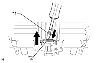
Text in Illustration *1 Protective Tape *2 Stopper
-
Using a screwdriver, push the stopper of the glove compartment door lock cylinder as shown in the illustration and remove the glove compartment door lock cylinder in the direction of the arrow.
Tech Tips
Tape the screwdriver tip before use.
-