COMPRESSOR (for 1AZ-FE) INSTALLATION

-
ADJUST AMOUNT OF COMPRESSOR OIL
-
When replacing the compressor assembly with a new one:
Drain the following amount of compressor oil from the new compressor to be installed to adjust the amount of compressor oil.
Standard (Amount of oil to be drained when replacing) 50 cc (1.7 fl.oz) Note
-
Since compressor oil remains in the pipes of the vehicle, if a new compressor is installed without removing some oil from the compressor, the oil amount becomes excessive. Excessive oil prevents heat exchange in the refrigerant cycle and causes refrigeration system failure.
-
Be sure to use ND-OIL 8 or equivalent for compressor oil.
-
Discharge the inert gas (helium) from the service valve.
-
Remove the suction seal cap.
-
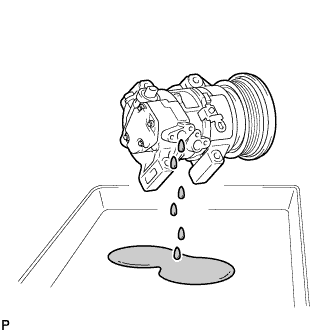
Position the suction port downward and slightly shake the compressor to drain oil.*1
Note
Be careful not to allow compressor oil to adhere to the pulley.
-
-
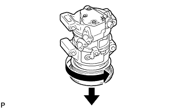
Position the pulley side downward and turn the pulley in the direction indicated by the arrow once every 2 seconds 10 times.*2
Note
Keep your face away from the compressor port because turning the pulley may cause gas or oil to spew out.
-
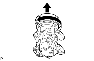
Quickly position the pulley side upward and turn the pulley in the direction indicated by the arrow once.*3
-
Repeat procedure *1.*4
-
Repeat procedures *2 through *4 about 5 times to drain the standard amount of oil.
-
-
INSTALL COMPRESSOR ASSEMBLY WITH PULLEY
-
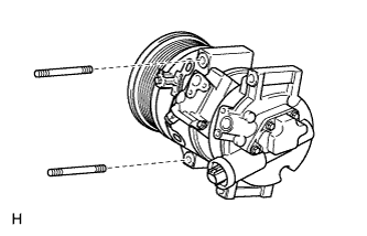
Using a "TORX" socket wrench (E8), install the compressor assembly with pulley with the 2 stud bolts.
- Torque:
- 9.8 N*m { 100 kgf*cm, 87 in.*lbf }
-
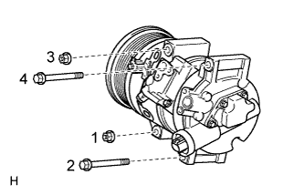
Install the 2 bolts and 2 nuts.
Tech Tips
Tighten the bolts and nuts in the order shown in the illustration.
- Torque:
- 25 N*m { 255 kgf*cm, 18 ft.*lbf }
-
Connect the connector.
-
Attach the 2 clamps.
-
-
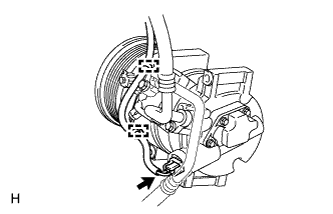
CONNECT SUCTION HOSE SUB-ASSEMBLY
-
Remove the attached vinyl tape from the hose and compressor.
-
Apply sufficient compressor oil to a new O-ring and the fitting surface of the compressor assembly with pulley.
Compressor oil ND-OIL 8 or equivalent -
Install the O-ring onto the suction hose sub-assembly.
-
Install the suction hose sub-assembly onto the compressor assembly with pulley with the bolt.
- Torque:
- 9.8 N*m { 100 kgf*cm, 87 in.*lbf }
-
-
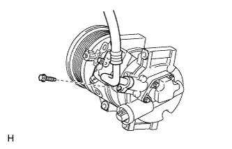
CONNECT DISCHARGE HOSE SUB-ASSEMBLY
-
Remove the attached vinyl tape from the hose and compressor.
-
Apply sufficient compressor oil to a new O-ring and the fitting surface of the compressor assembly with pulley.
Compressor oil ND-OIL 8 or equivalent -
Install the O-ring onto the discharge hose sub-assembly.
-
Install the discharge hose sub-assembly onto the compressor assembly with pulley with the bolt.
- Torque:
- 9.8 N*m { 100 kgf*cm, 87 in.*lbf }
-
-
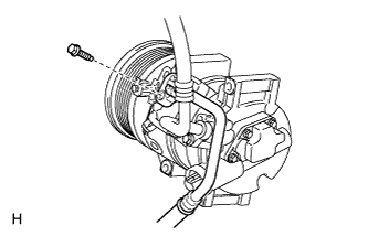
INSTALL V-RIBBED BELT
Tech Tips
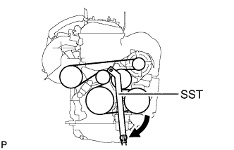
The illustration shows the belt layout.
-
Using SST, slowly turn the V-ribbed belt tensioner clockwise and install the belt.
- SST
- 09216-42010
Note
-
Make sure that SST and other tools are set to the tensioner securely.
-
When compressing the V-ribbed belt tensioner, slowly turn the tensioner.
-
-
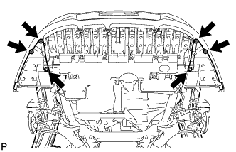
INSTALL FRONT SUSPENSION MEMBER REINFORCEMENT RH
-
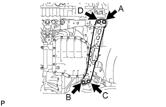
Install the front suspension member reinforcement LH with the 8 bolts.
- Torque:
- 96 N*m { 979 kgf*cm, 71 ft.*lbf }
Note
Tighten the bolts in the order of C, B, D and A.
-
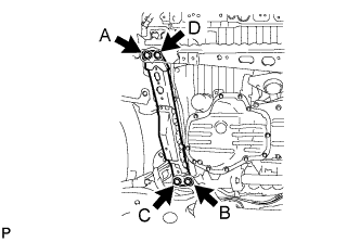
Install the front suspension member reinforcement RH with the 8 bolts.
- Torque:
- 96 N*m { 979 kgf*cm, 71 ft.*lbf }
Note
Tighten the bolts in the order of C, B, D and A.
-
-
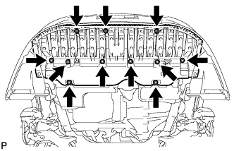
INSTALL ENGINE UNDER COVER REAR RH
-
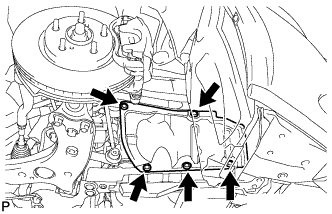
Install the under cover with the 5 clips.
-
-
INSTALL NO. 1 ENGINE UNDER COVER
-
Install the under cover with the 5 clips.
-
-
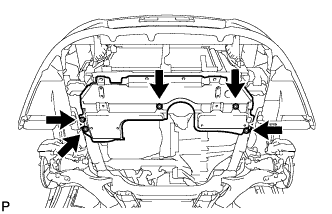
INSTALL FRONT COVER BUMPER ABSORBER
-
Install the front lower bumper absorber with the 8 bolts and 3 screws.
-
Install the 4 screws and 2 bolts.
-
-
CHARGE REFRIGERANT
- SST
- 09985-20010 ( 09985-02130, 09985-02150, 09985-02090, 09985-02110, 09985-02010, 09985-02050, 09985-02060, 09985-02070 )
-
Perform vacuum purging using a vacuum pump.
-
Charge refrigerant HFC-134a (R134a).
Standard 440 +/-30 g (15.5 +/-1.1 oz) 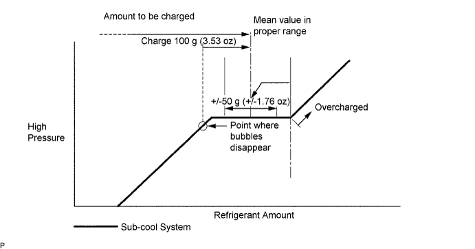
Note
-
Do not operate the cooler compressor before charging refrigerant as the cooler compressor will not work properly without any refrigerant, and will overheat.
-
Approximately 200 g (7.05 oz) of refrigerant may need to be charged after bubbles disappear. The refrigerant amount should be checked by measuring its quantity, and not with the sight glass.
-
-
WARM UP ENGINE
-
Warm up the engine at less than 1850 rpm for 2 minutes or more after charging the refrigerant.
Note
Be sure to warm up the compressor when turning the A/C switch on after removing and installing the cooler refrigerant lines (including the compressor) to prevent damage to the compressor.
-
-
INSPECT FOR REFRIGERANT LEAK
-
After recharging the refrigerant gas, check for refrigerant gas leakage using a halogen leak detector.
-
Perform the operation observing the following instructions:
-
Stop the engine.
-
Secure good ventilation (the halogen leak detector may react to volatile gases other than refrigerant, such as evaporated gasoline or exhaust gas).
-
Repeat the test 2 or 3 times.
-
Make sure that some refrigerant remains in the refrigeration system.
Tech Tips
When the compressor is off: approximately 392 to 588 kPa (4.0 to 6.0 kgf/cm2, 57 to 85 psi).
-
-
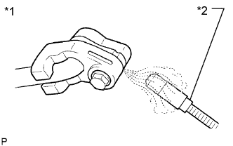
Text in Illustration *1 Check for Leakage *2 Halogen Leak Detector Using a halogen leak detector, check the refrigerant line for leakage.
-
If a gas leak is not detected from the drain hose, remove the blower motor control (blower resistor) from the cooling unit. Insert the halogen leak detector sensor into the unit and check for gas leakage.
-
Disconnect the pressure switch connector and wait for approximately 20 minutes. Bring the halogen leak detector close to the pressure switch and check for gas leakage.
-
-
INSTALL RADIATOR SUPPORT OPENING COVER
-
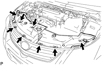
Install the radiator support opening cover with the 8 clips.
-
-
INSTALL ENGINE ROOM SIDE COVER
-
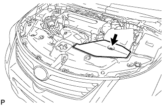
Install the engine room side cover with the clip.
-
-
INSTALL NO. 1 ENGINE COVER
-
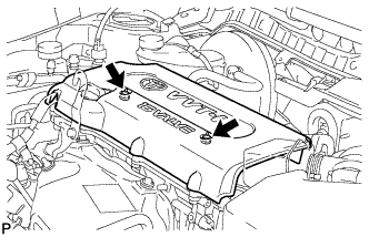
Install the cover with the 2 nuts.
- Torque:
- 9.0 N*m { 92 kgf*cm, 80 in.*lbf }
-