COMPRESSOR (for 1AZ-FE) REMOVAL

-
REMOVE NO. 1 ENGINE COVER
-
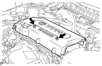
Remove the 2 nuts and engine cover.
-
-
REMOVE ENGINE ROOM SIDE COVER
-
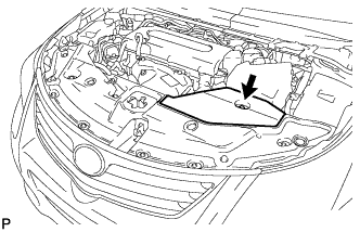
Remove the clip and engine room side cover.
-
-
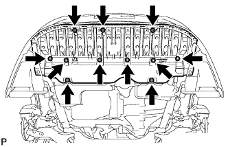
REMOVE RADIATOR SUPPORT OPENING COVER
-
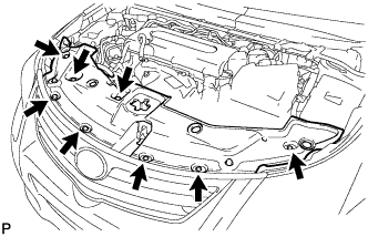
Remove the 8 clips and radiator support opening cover.
-
-
RECOVER REFRIGERANT FROM REFRIGERATION SYSTEM
-
Start the engine.
-
Turn the A/C switch on.
-
Operate the cooler compressor while the engine speed is approximately 1000 rpm for 5 to 6 minutes to circulate the refrigerant and collect the compressor oil remaining in each component into the cooler compressor.
-
Stop the engine.
-
Recover the refrigerant from the A/C system using a refrigerant recovery unit.
-
-
REMOVE FRONT COVER BUMPER ABSORBER
-
Remove the 4 screws and 2 bolts.
Tech Tips
Pull down the fender liner so that the front lower bumper absorber can be removed in the next step.
-
Remove the 3 screws, 8 bolts and front lower bumper absorber.
-
-
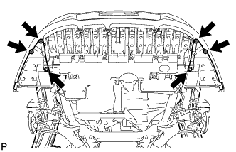
REMOVE NO. 1 ENGINE UNDER COVER
-
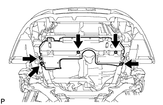
Remove the 5 clips and under cover.
-
-
REMOVE ENGINE UNDER COVER REAR RH
-
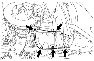
Remove the 5 clips and under cover.
-
-
REMOVE FRONT SUSPENSION MEMBER REINFORCEMENT RH
-
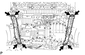
Remove the 8 bolts and 2 front suspension member reinforcements.
-
-
REMOVE V-RIBBED BELT
-
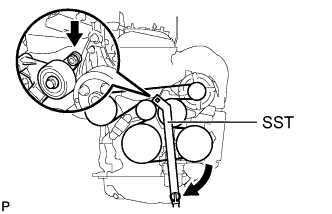
Using SST, slowly turn the V-ribbed belt tensioner clockwise.
- SST
- 09216-42010
CAUTION:
Be careful not to pinch your fingers between the parts.
Note
-
Make sure that SST and other tools are set to the tensioner securely.
-
When compressing the V-ribbed belt tension, slowly turn the tensioner.
-
Remove the belt from each pulley and slowly return the tensioner.
CAUTION:
Be careful not to pinch your fingers between the parts.
-
-
DISCONNECT DISCHARGE HOSE SUB-ASSEMBLY
-
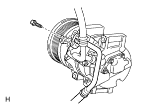
Remove the bolt and disconnect the discharge hose sub-assembly from the compressor assembly with pulley.
Note
Seal the openings of the disconnected parts using vinyl tape to prevent entry of moisture and foreign matter.
-
Remove the O-ring from the discharge hose sub-assembly.
Note
Seal the openings of the disconnected parts using vinyl tape to prevent entry of moisture and foreign matter.
-
-
DISCONNECT SUCTION HOSE SUB-ASSEMBLY
-
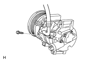
Remove the bolt and disconnect the suction hose sub-assembly from the compressor assembly with pulley.
Note
Seal the openings of the disconnected parts using vinyl tape to prevent entry of moisture and foreign matter.
-
Remove the O-ring from the suction hose sub-assembly.
Note
Seal the openings of the disconnected parts using vinyl tape to prevent entry of moisture and foreign matter.
-
-
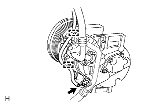
REMOVE COMPRESSOR ASSEMBLY WITH PULLEY
-
Detach the 2 clamps.
-
Disconnect the connector.
-
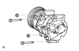
Remove the 2 bolts and 2 nuts.
-
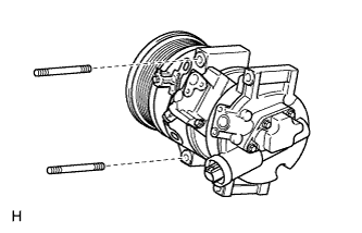
Using a "TORX" socket wrench (E8), remove the 2 stud bolts and the compressor assembly with pulley.
-