CONDENSER REMOVAL

-
REMOVE ENGINE ROOM SIDE COVER
-
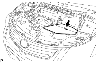
Remove the clip and engine room side cover.
-
-
REMOVE RADIATOR SUPPORT OPENING COVER
-
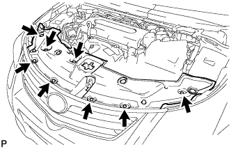
Remove the 8 clips and radiator support opening cover.
-
-
RECOVER REFRIGERANT FROM REFRIGERATION SYSTEM
-
Start the engine.
-
Turn the A/C switch on.
-
Operate the cooler compressor while the engine speed is approximately 1000 rpm for 5 to 6 minutes to circulate the refrigerant and collect the compressor oil remaining in each component into the cooler compressor.
-
Stop the engine.
-
Recover the refrigerant from the A/C system using a refrigerant recovery unit.
-
-
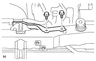
REMOVE NO. 1 WATER HOSE CLAMP BRACKET
-
Remove the 2 bolts and hose clamp bracket.
-
-
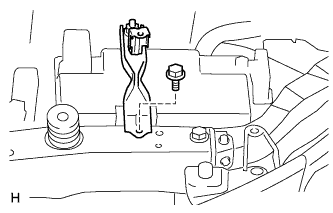
REMOVE BATTERY CLAMP SUB-ASSEMBLY
-
Remove the bolt and battery clamp.
-
-
REMOVE HOOD LOCK ASSEMBLY
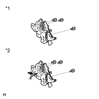
Text in Illustration *1 w/o Engine Hood Courtesy Switch *2 w/ Engine Hood Courtesy Switch
-
w/ Engine Hood Courtesy Switch:
Disconnect the connector.
-
Remove the 3 bolts and hood lock.
-
-
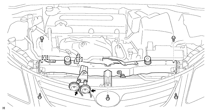
REMOVE RADIATOR SUPPORT UPPER
-
Disconnect the 2 horn connectors.
-
Detach the 2 clamps and remove the No. 2 water by-pass hose.
-
Remove the 5 bolts and radiator support upper.
-
-
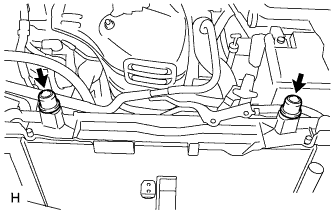
REMOVE RADIATOR SUPPORT CUSHION
-
Remove the 2 cushions.
-
-
REMOVE NO. 2 FAN SHROUD
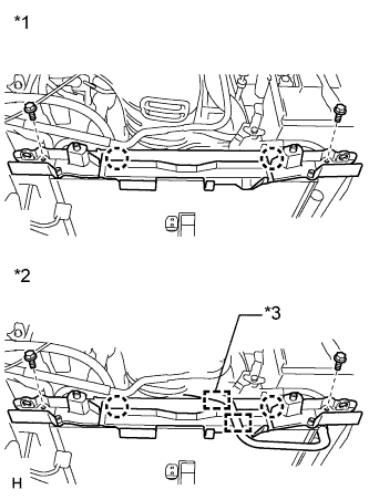
Text in Illustration *1 except ZR Series Engine *2 for ZR Series Engine *3 for Automatic Transaxle, CVT
-
for ZR Series Engine:
-
for Automatic Transaxle, CVT:
Detach the clamps and remove the No. 3 water by-pass hose.
-
for Manual Transaxle:
Detach the clamp and remove the No. 3 water by-pass hose.
-
-
Remove the 2 bolts.
-
Detach the 2 claws and remove the fan shroud.
-
-
DISCONNECT DISCHARGE HOSE SUB-ASSEMBLY
-
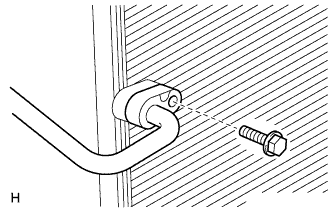
Remove the bolt and disconnect the discharge hose sub-assembly from the condenser.
Note
Seal the openings of the disconnected parts using vinyl tape to prevent entry of moisture and foreign matter.
-
Remove the O-ring from the discharge hose sub-assembly.
Note
Seal the openings of the disconnected parts using vinyl tape to prevent entry of moisture and foreign matter.
-
-
DISCONNECT SUCTION PIPE SUB-ASSEMBLY
-
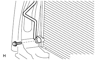
Remove the bolt and disconnect the suction pipe sub-assembly from the condenser.
Note
Seal the openings of the disconnected parts using vinyl tape to prevent entry of moisture and foreign matter.
-
Remove the O-ring from the suction pipe sub-assembly.
Note
Seal the openings of the disconnected parts using vinyl tape to prevent entry of moisture and foreign matter.
-
-
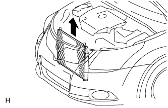
REMOVE CONDENSER ASSEMBLY WITH RECEIVER
-
Remove the condenser assembly with receiver as shown in the illustration.
-