AIR CONDITIONING SYSTEM (for Automatic Air Conditioning System) Generator Signal Circuit
DESCRIPTION
When the engine is started, the generator assembly turns and a pulsed voltage signal is generated.
This signal is used by the air conditioning amplifier assembly.
The signal expressing the amount of output from the generator assembly is one element of PTC heater control.
WIRING DIAGRAM
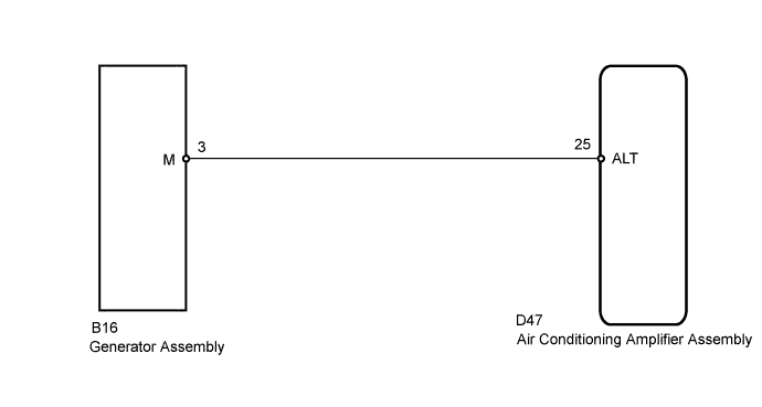
INSPECTION PROCEDURE
PROCEDURE
-
CHECK HARNESS AND CONNECTOR (AIR CONDITIONING AMPLIFIER - GENERATOR)
-
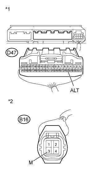
Text in Illustration *1 Rear view of wire harness connector
(to Air Conditioning Amplifier Assembly)
*2 Front view of wire harness connector
(to Generator Assembly)
Disconnect the D47 amplifier connector.
-
Disconnect the B16 generator connector.
-
Measure the resistance according to the value(s) in the table below.
Standard Resistance Tester Connection Condition Specified Condition D47-25 (ALT) - B16-3 (M) Always Below 1 Ω D47-25 (ALT) - Body ground Always 10 kΩ or higher
NG 
REPAIR OR REPLACE HARNESS OR CONNECTOR
OK 
-
-
CHECK MODEL
-
Check the engine model.
Result Result Proceed to 1AZ-FE, 3ZR-FE A 1ZR-FAE, 2ZR-FAE, 3ZR-FAE B
B 
INSPECT GENERATOR ASSEMBLY Click here
A
-
-
INSPECT GENERATOR ASSEMBLY
-
for 1AZ-FE:
Inspect the generator assembly Click here.
-
for 3ZR-FE:
Inspect the generator assembly Click here.
Result Result Proceed to OK A NG (for 1AZ-FE) B NG (for 3ZR-FE) C
B
REPLACE GENERATOR ASSEMBLY Click here
C
REPLACE GENERATOR ASSEMBLY Click here
A 
PROCEED TO NEXT SUSPECTED AREA SHOWN IN PROBLEM SYMPTOMS TABLE Click here
-
-
INSPECT GENERATOR ASSEMBLY
-
for 1ZR-FAE:
Inspect the generator assembly Click here.
-
for 2ZR-FAE:
Inspect the generator assembly Click here.
-
for 3ZR-FAE:
Inspect the generator assembly Click here.
Result Result Proceed to OK A NG (for 1ZR-FAE) B NG (for 2ZR-FAE) C NG (for 3ZR-FAE) D
B
REPLACE GENERATOR ASSEMBLY Click here
C
REPLACE GENERATOR ASSEMBLY Click here
D
REPLACE GENERATOR ASSEMBLY Click here
A
PROCEED TO NEXT SUSPECTED AREA SHOWN IN PROBLEM SYMPTOMS TABLE Click here
-