METER / GAUGE SYSTEM Speed Signal Circuit
DESCRIPTION
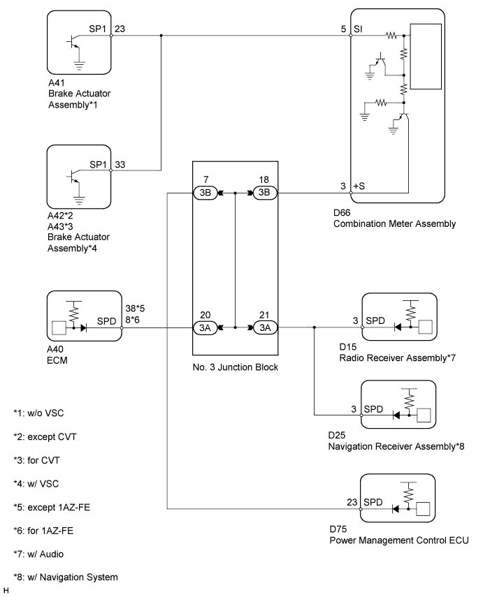
The vehicle speed sensor signal consists of pulses sent to the combination meter assembly from the skid control ECU.
WIRING DIAGRAM
INSPECTION PROCEDURE
PROCEDURE
-
CHECK ECU TERMINAL VOLTAGE (INPUT VOLTAGE)
-
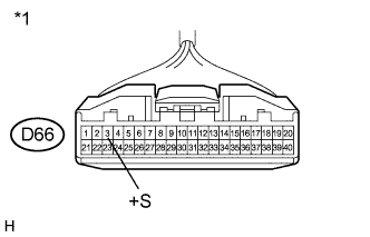
Text in Illustration *1 Front view of wire harness connector
(to Combination Meter Assembly)
Disconnect the D66 meter connector.
-
Measure the voltage according to the value(s) in the table below.
Standard Voltage Tester Connection Switch Condition Specified Condition D66-3 (+S) - Body ground Ignition switch ON 4.5 to 14 V Tech Tips
If any of the ECUs specified in the wiring diagram supplies power to the combination meter assembly, the combination meter assembly will output a waveform.
NG 
CHECK HARNESS AND CONNECTOR (COMBINATION METER ASSEMBLY - NO. 3 JUNCTION BLOCK) Click here
OK 
-
-
CHECK COMBINATION METER ASSEMBLY (OUTPUT VOLTAGE)
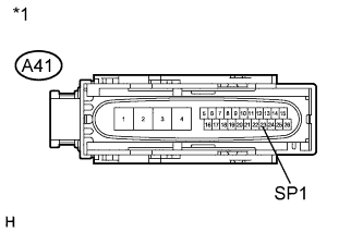
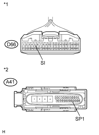
Text in Illustration *1 Front view of wire harness connector
(to Brake Actuator Assembly)
-
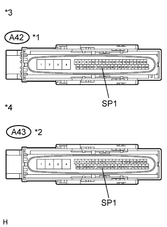
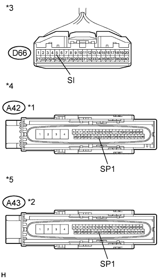
Text in Illustration *1 except CVT *2 for CVT *3 Front view of wire harness connector
(to Brake Actuator Assembly)
*4 Front view of wire harness connector
(to Brake Actuator Assembly)
w/o VSC:
-
Disconnect the A41 brake actuator connector.
-
Measure the voltage according to the value(s) in the table below.
Standard Voltage Tester Connection Switch Condition Specified Condition A41-23 (SP1) - Body ground Ignition switch ON 11 to 14 V
-
-
w/ VSC:
-
Disconnect the A42*1 or A43*2 brake actuator connector.
*1: except CVT
*2: for CVT
-
Measure the voltage according to the value(s) in the table below.
Standard Voltage Tester Connection Switch Condition Specified Condition A42-33*1 (SP1) - Body ground Ignition switch ON 11 to 14 V A43-33*2 (SP1) - Body ground *1: except CVT
*2: for CVT
-
NG
CHECK HARNESS AND CONNECTOR (COMBINATION METER ASSEMBLY - SKID CONTROL ECU) Click here
OK
-
-
CHECK COMBINATION METER ASSEMBLY (SPEED SIGNAL)
-
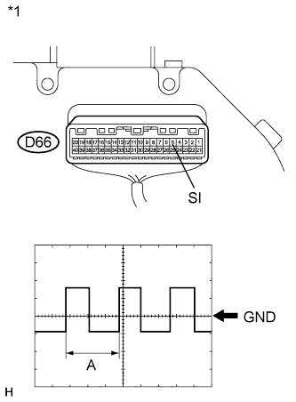
Text in Illustration *1 Component with harness connected
(Combination Meter Assembly)
Check the input waveform.
-
Reconnect the D66 meter connector.
-
Remove the combination meter assembly with the connector(s) still connected.
-
Connect an oscilloscope to terminal D66-5 (SI) and body ground.
-
Turn the ignition switch to ON.
-
Turn the wheel slowly.
-
Check the signal waveform according to the condition(s) in the table below.
Measurement Condition Item Condition Terminal No. (Symbols) D66-5 (SI) - Body ground Tool setting 5 V/DIV., 20 ms./DIV. Condition Being driven at approx. 20 km/h (12 mph) OK The waveform is displayed as shown in the illustration. Tech Tips
When the system is functioning normally, one wheel revolution generates 4 pulses. As the vehicle speed increases, the width indicated by (A) in the illustration narrows.
Result Result Proceed to OK A NG (w/o VSC) B NG (w/ VSC) C
-
B 
REPLACE BRAKE ACTUATOR ASSEMBLY Click here
C
REPLACE BRAKE ACTUATOR ASSEMBLY Click here
A 
REPLACE COMBINATION METER ASSEMBLY Click here
-
-
CHECK HARNESS AND CONNECTOR (COMBINATION METER ASSEMBLY - SKID CONTROL ECU)
-
Text in Illustration *1 Front view of wire harness connector
(to Combination Meter Assembly)
*2 Front view of wire harness connector
(to Brake Actuator Assembly)
w/o VSC:
-
Disconnect the D66 meter connector.
-
Disconnect the A41 brake actuator connector.
-
Measure the resistance according to the value(s) in the table below.
Standard Resistance Tester Connection Condition Specified Condition D66-5 (SI) - A41-23 (SP1) Always Below 1 Ω A41-23 (SP1) - Body ground Always 10 kΩ or higher
-
-
Text in Illustration *1 except CVT *2 for CVT *3 Front view of wire harness connector
(to Combination Meter Assembly)
*4 Front view of wire harness connector
(to Brake Actuator Assembly)
*5 Front view of wire harness connector
(to Brake Actuator Assembly)
w/ VSC:
-
Disconnect the D66 meter connector.
-
Disconnect the A42*1 or A43*2 brake actuator connectors.
*1: except CVT
*2: for CVT
-
Measure the resistance according to the value(s) in the table below.
Standard Resistance Tester Connection Condition Specified Condition D66-5 (SI) - A42-33*1 (SP1) Always Below 1 Ω A42-33*14 (SP1) - Body ground Always 10 kΩ or higher D66-5 (SI) - A43-33*2 (SP1) Always Below 1 Ω A43-33*2 (SP1) - Body ground Always 10 kΩ or higher *1: except CVT
*2: for CVT
-
NG
REPAIR OR REPLACE HARNESS OR CONNECTOR
OK
REPLACE COMBINATION METER ASSEMBLY Click here
-
-
CHECK HARNESS AND CONNECTOR (COMBINATION METER ASSEMBLY - NO. 3 JUNCTION BLOCK)
-
Disconnect the D66 meter connector.
-
Disconnect the 3B junction block connector.
-
Measure the resistance according to the value(s) in the table below.
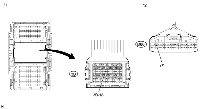
Standard Resistance Tester Connection Condition Specified Condition D66-3 (+S) - 3B-18 Always Below 1 Ω D66-3 (+S) - Body ground Always 10 kΩ or higher Text in Illustration *1 Front view of wire harness connector
(to No. 3 Junction Block)
*2 Front view of wire harness connector
(to Combination Meter Assembly)
NG
REPAIR OR REPLACE HARNESS OR CONNECTOR
OK
-
-
CHECK POWER MANAGEMENT CONTROL ECU
-
Disconnect the 3B junction block connector.
-
Measure the voltage according to the value(s) in the table below.
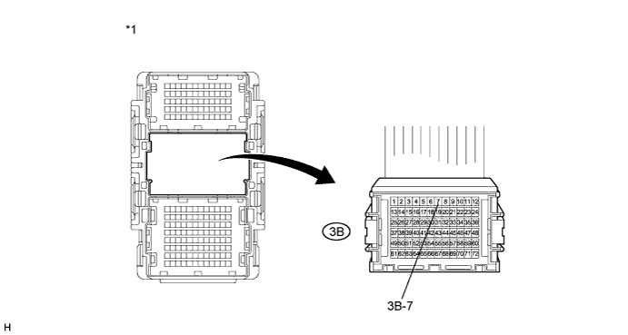
Standard Voltage Tester Connection Switch Condition Specified Condition 3B-7 - Body ground Ignition switch ON 4.5 to 14 V Text in Illustration *1 Front view of wire harness connector
(to No. 3 Junction Block)
NG
CHECK HARNESS AND CONNECTOR (POWER MANAGEMENT CONTROL ECU CIRCUIT) Click here
OK
-
-
CHECK RADIO RECEIVER ASSEMBLY

-
Disconnect the 3A junction block connector.
-
Measure the voltage according to the value(s) in the table below.
Standard Voltage Tester Connection Switch Condition Specified Condition 3A-21 - Body ground Ignition switch ON 4.5 to 14 V Text in Illustration *1 Front view of wire harness connector
(to No. 3 Junction Block)
NG
CHECK HARNESS AND CONNECTOR (RADIO RECEIVER ASSEMBLY CIRCUIT) Click here
OK
-
-
CHECK NAVIGATION RECEIVER ASSEMBLY
-
Disconnect the 3A junction block connector.
-
Measure the voltage according to the value(s) in the table below.
Standard Voltage Tester Connection Switch Condition Specified Condition 3A-21 - Body ground Ignition switch ON 4.5 to 14 V Text in Illustration *1 Front view of wire harness connector
(to No. 3 Junction Block)
NG
CHECK HARNESS AND CONNECTOR (NAVIGATION RECEIVER ASSEMBLY CIRCUIT) Click here
OK
-
-
CHECK ENGINE TYPE
-
Check the engine type.
Engine Type Proceed to 1AZ-FE A 1ZR-FAE B 2ZR-FAE C 3ZR-FE D 3ZR-FAE E
B
CHECK ECM (for 1ZR-FAE) Click here
C
CHECK ECM (for 2ZR-FAE) Click here
D
CHECK ECM (for 3ZR-FE) Click here
E
CHECK ECM (for 3ZR-FAE) Click here
A
-
-
CHECK ECM (for 1AZ-FE)
-
Disconnect the 3A junction block connector.
-
Measure the voltage according to the value(s) in the table below.
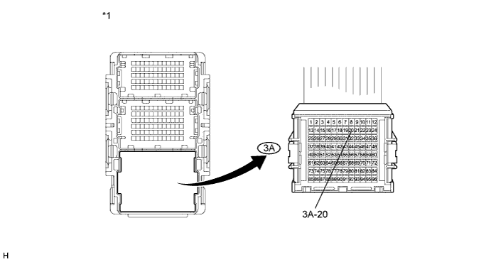
Standard Voltage Tester Connection Switch Condition Specified Condition 3A-20 - Body ground Ignition switch ON 4.5 to 14 V Text in Illustration *1 Front view of wire harness connector
(to No. 3 Junction Block)
NG
CHECK HARNESS AND CONNECTOR (ECM CIRCUIT (for 1AZ-FE)) Click here
OK
REPLACE NO. 3 JUNCTION BLOCK
-
-
CHECK ECM (for 1ZR-FAE)
-
Disconnect the 3A junction block connector.
-
Measure the voltage according to the value(s) in the table below.
Standard Voltage Tester Connection Switch Condition Specified Condition 3A-20 - Body ground Ignition switch ON 4.5 to 14 V Text in Illustration *1 Front view of wire harness connector
(to No. 3 Junction Block)
NG
CHECK HARNESS AND CONNECTOR (ECM CIRCUIT (for 1ZR-FAE)) Click here
OK
REPLACE NO. 3 JUNCTION BLOCK
-
-
CHECK ECM (for 2ZR-FAE)
-
Disconnect the 3A junction block connector.
-
Measure the voltage according to the value(s) in the table below.
Standard Voltage Tester Connection Switch Condition Specified Condition 3A-20 - Body ground Ignition switch ON 4.5 to 14 V Text in Illustration *1 Front view of wire harness connector
(to No. 3 Junction Block)
NG
CHECK HARNESS AND CONNECTOR (ECM CIRCUIT (for 2ZR-FAE)) Click here
OK
REPLACE NO. 3 JUNCTION BLOCK
-
-
CHECK ECM (for 3ZR-FE)
-
Disconnect the 3A junction block connector.
-
Measure the voltage according to the value(s) in the table below.
Standard Voltage Tester Connection Switch Condition Specified Condition 3A-20 - Body ground Ignition switch ON 4.5 to 14 V Text in Illustration *1 Front view of wire harness connector
(to No. 3 Junction Block)
NG
CHECK HARNESS AND CONNECTOR (ECM CIRCUIT (for 3ZR-FE)) Click here
OK
REPLACE NO. 3 JUNCTION BLOCK
-
-
CHECK ECM (for 3ZR-FAE)
-
Disconnect the 3A junction block connector.
-
Measure the voltage according to the value(s) in the table below.
Standard Voltage Tester Connection Switch Condition Specified Condition 3A-20 - Body ground Ignition switch ON 4.5 to 14 V Text in Illustration *1 Front view of wire harness connector
(to No. 3 Junction Block)
NG
CHECK HARNESS AND CONNECTOR (ECM CIRCUIT (for 3ZR-FAE)) Click here
OK
REPLACE NO. 3 JUNCTION BLOCK
-
-
CHECK HARNESS AND CONNECTOR (POWER MANAGEMENT CONTROL ECU CIRCUIT)
-
Disconnect the 3B junction block connector.
-
Disconnect the D75 power management control ECU connector.
-
Measure the resistance according to the value(s) in the table below.
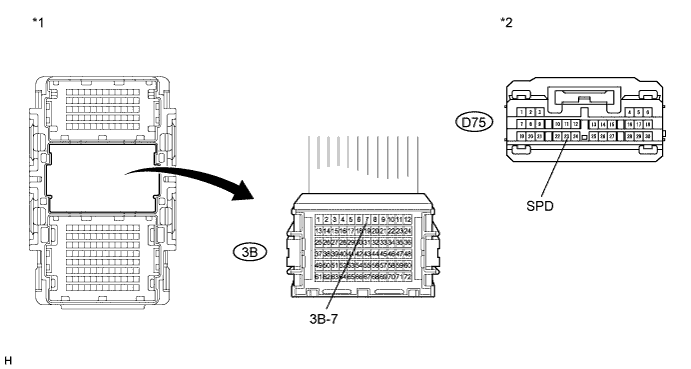
Standard Resistance Tester Connection Condition Specified Condition D75-23 (SPD) - 3B-7 Always Below 1 Ω 3B-7 - Body ground Always 10 kΩ or higher Text in Illustration *1 Front view of wire harness connector
(to No. 3 Junction Block)
*2 Front view of wire harness connector
(to Power Management Control ECU)
NG
REPAIR OR REPLACE HARNESS OR CONNECTOR
OK
REPLACE POWER MANAGEMENT CONTROL ECU Click here
-
-
CHECK HARNESS AND CONNECTOR (RADIO RECEIVER ASSEMBLY CIRCUIT)
-
Disconnect the 3A junction block connector.
-
Disconnect the D15 radio receiver assembly connector.
-
Measure the resistance according to the value(s) in the table below.
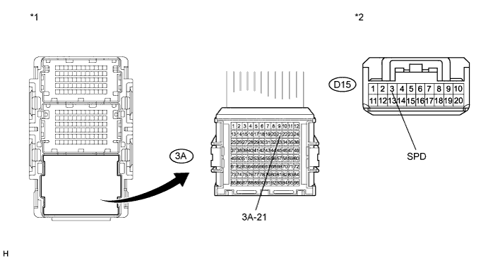
Standard Resistance Tester Connection Condition Specified Condition D15-3 (SPD) - 3A-21 Always Below 1 Ω 3A-21 - Body ground Always 10 kΩ or higher Text in Illustration *1 Front view of wire harness connector
(to No. 3 Junction Block)
*2 Front view of wire harness connector
(to Radio Receiver Assembly)
NG
REPAIR OR REPLACE HARNESS OR CONNECTOR
OK
REPLACE RADIO RECEIVER ASSEMBLY Click here
-
-
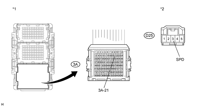
CHECK HARNESS AND CONNECTOR (NAVIGATION RECEIVER ASSEMBLY CIRCUIT)
-
Disconnect the 3A junction block connector.
-
Disconnect the D25 navigation receiver connector.
-
Measure the resistance according to the value(s) in the table below.
Standard Resistance Tester Connection Condition Specified Condition D25-3 (SPD) - 3A-21 Always Below 1 Ω 3A-21 - Body ground Always 10 kΩ or higher Text in Illustration *1 Front view of wire harness connector
(to No. 3 Junction Block)
*2 Front view of wire harness connector
(to Navigation Receiver Assembly)
Result Result Proceed to OK (w/ Navigation System for DVD) A OK (w/ Navigation System for HDD) B NG C
B
REPLACE NAVIGATION RECEIVER ASSEMBLY Click here
C
REPAIR OR REPLACE HARNESS OR CONNECTOR
A
REPLACE NAVIGATION RECEIVER ASSEMBLY Click here
-
-
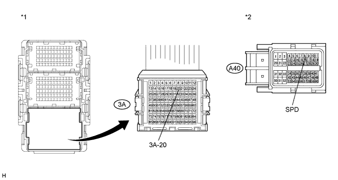
CHECK HARNESS AND CONNECTOR (ECM CIRCUIT (for 1AZ-FE))
-
Disconnect the 3A junction block connector.
-
Disconnect the A40 ECM connector.
-
Measure the resistance according to the value(s) in the table below.
Standard Resistance Tester Connection Condition Specified Condition A40-8 (SPD) - 3A-20 Always Below 1 Ω 3A-20 - Body ground Always 10 kΩ or higher Text in Illustration *1 Front view of wire harness connector
(to No. 3 Junction Block)
*2 Front view of wire harness connector
(to ECM)
NG
REPAIR OR REPLACE HARNESS OR CONNECTOR
OK
REPLACE ECM Click here
-
-
CHECK HARNESS AND CONNECTOR (ECM CIRCUIT (for 1ZR-FAE))

-
Disconnect the 3A junction block connector.
-
Disconnect the A40 ECM connector.
-
Measure the resistance according to the value(s) in the table below.
Standard Resistance Tester Connection Condition Specified Condition A40-38 (SPD) - 3A-20 Always Below 1 Ω 3A-20 - Body ground Always 10 kΩ or higher Text in Illustration *1 Front view of wire harness connector
(to No. 3 Junction Block)
*2 Front view of wire harness connector
(to ECM)
NG
REPAIR OR REPLACE HARNESS OR CONNECTOR
OK
REPLACE ECM Click here
-
-
CHECK HARNESS AND CONNECTOR (ECM CIRCUIT (for 2ZR-FAE))
-
Disconnect the 3A junction block connector.
-
Disconnect the A40 ECM connector.
-
Measure the resistance according to the value(s) in the table below.
Standard Resistance Tester Connection Condition Specified Condition A40-38 (SPD) - 3A-20 Always Below 1 Ω 3A-20 - Body ground Always 10 kΩ or higher Text in Illustration *1 Front view of wire harness connector
(to No. 3 Junction Block)
*2 Front view of wire harness connector
(to ECM)
NG
REPAIR OR REPLACE HARNESS OR CONNECTOR
OK
REPLACE ECM Click here
-
-
CHECK HARNESS AND CONNECTOR (ECM CIRCUIT (for 3ZR-FE))
-
Disconnect the 3A junction block connector.
-
Disconnect the A40 ECM connector.
-
Measure the resistance according to the value(s) in the table below.
Standard Resistance Tester Connection Condition Specified Condition A40-38 (SPD) - 3A-20 Always Below 1 Ω 3A-20 - Body ground Always 10 kΩ or higher Text in Illustration *1 Front view of wire harness connector
(to No. 3 Junction Block)
*2 Front view of wire harness connector
(to ECM)
NG
REPAIR OR REPLACE HARNESS OR CONNECTOR
OK
REPLACE ECM Click here
-
-
CHECK HARNESS AND CONNECTOR (ECM CIRCUIT (for 3ZR-FAE))
-
Disconnect the 3A junction block connector.
-
Disconnect the A40 ECM connector.
-
Measure the resistance according to the value(s) in the table below.
Standard Resistance Tester Connection Condition Specified Condition A40-38 (SPD) - 3A-20 Always Below 1 Ω 3A-20 - Body ground Always 10 kΩ or higher Text in Illustration *1 Front view of wire harness connector
(to No. 3 Junction Block)
*2 Front view of wire harness connector
(to ECM)
NG
REPAIR OR REPLACE HARNESS OR CONNECTOR
OK
REPLACE ECM Click here
-