METER / GAUGE SYSTEM SYSTEM DESCRIPTION

-
METER GAUGE AND WARNING/INDICATOR
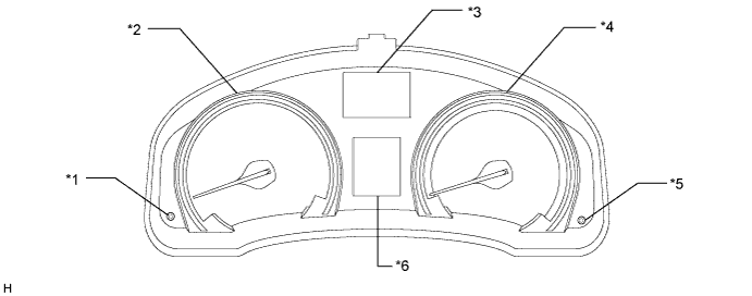
Text in Illustration *1 ODO/TRIP Switch *4 Speedometer *2 Tachometer *5 Rheostat Switch *3 Multi-information Display *6
-
Fuel Receiver Gauge
-
Engine Coolant Temperature Receiver Gauge
-
Clock Display
-
Automatic Transaxle Display (for Automatic Transaxle and CVT)
Meter/Gauge Item Details Speedometer Based on a signal received from the wheel speed sensor, the skid control ECU calculates the vehicle speed and transmits data to the combination meter (CAN). Tachometer The combination meter receives an engine speed signal from the ECM and the gauge needle operates (CAN). ODO/TRIP meter
-
The combination meter receives a vehicle speed pulse integration signal from the skid control ECU and the ODO/TRIP meter display operates (CAN).
-
The ODO/TRIP meter display changes when the ODO/TRIP switch is operated.
Fuel receiver gauge The combination meter receives fuel amount information measured by the fuel sender gauge and the gauge needle operates (Direct line). Engine coolant temperature receiver gauge The combination meter receives an engine coolant temperature signal from the ECM and the gauge needle operates (CAN). Warning/Indicator Item Details BEAM indicator light

Receives BEAM indicator light signals from the main body ECU (CAN). FRONT FOG indicator light*1

The indicator turns on when a FRONT FOG illumination command signal is received (CAN). REAR FOG indicator light*2

The indicator turns on when a REAR FOG illumination command signal is received (CAN). SRS warning light

Receives malfunction signals from the center airbag sensor (CAN). Driver side seat belt warning light

Receives driver seat belt signals (unfastened) from the main body ECU (CAN). Brake system warning light (Yellow indicator)

Comes on when the electric parking brake system is malfunctioning. (Direct Line). Brake system warning light (Red indicator)
Comes on when the brake fluid level warning switch is on (CAN). CHARGE warning light

Receives malfunction signals from the generator (Direct line and CAN). ABS warning light

Receives malfunction signals from the skid control ECU (CAN). MIL

Receives malfunction signals from the ECM (Direct line). AFS OFF indicator light*3

Receives AFS OFF indicator signals from the headlight swivel ECU (CAN). FUEL warning light

Receives fuel empty signals from the fuel sender gauge (Direct line). SLIP indicator light*4

Receives malfunction signals from the skid control ECU (CAN). TAIL indicator light

The indicator turns on when a taillight illumination signal is received (CAN). Turn signal indicator light (LH/RH)

Receives a turn signal from the FLASHER relay (Direct line). EPS warning light

Receives power steering warning signals from power steering ECU (CAN) Master warning light

Receives warning signals from sensors and ECUs (Direct line and CAN). PARK warning light

Comes on when the parking brake switch is on (Direct line). SIL indicator (UP/DOWN)*5

Receives a shift signal from the ECM (CAN). Eco driving indicator light*6, *8

Receives an eco driving indicator light signal from the ECM (CAN (CAN No. 1 Bus)) and illuminates when the vehicle is being driven economically. Cruise indicator*7

Receives a cruise control switch signal from the ECM (CAN). Speed limiter indicator*7

Receives a warning canceling switch signal from the ECM (CAN). Cruise set indicator*7

Receives a cruise control switch from the ECM (CAN). A/T P shift position indicator*6, *8 Receives a P signal from the ECM (CAN). A/T R shift position indicator*6, *8 Receives an R signal from the ECM (CAN). A/T N shift position indicator*6, *8 Receives an N signal from the ECM (CAN). A/T D shift position indicator*6, *8 Receives a D signal from the ECM (CAN). A/T S (1 to 4) shift position indicator*6 Receives a signal (1 to 4) from the ECM (CAN). A/T S (1 to 7) shift position indicator*8 Receives a signal (1 to 7) from the ECM (CAN). *1: w/ Front Fog light
*2: w/ Rear Fog light
*3: w/ Adaptive Front-lighting System
*4: w/ VSC
*5: for Manual Transaxle
*6: for Automatic Transaxle and Unleaded Gasoline Specification Vehicle
*7: w/ Cruise Control System
*8: for CVT
-
-
MULTI-INFORMATION DISPLAY
-
Operation using the ODO/TRIP switch or the display switch of the steering pad switch.
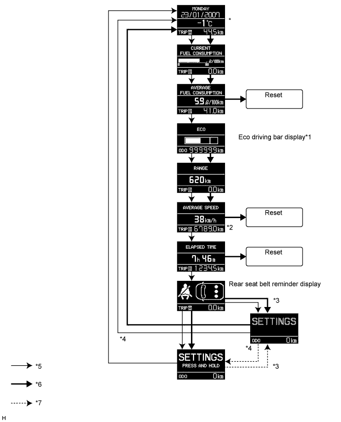
Tech Tips
After the ignition switch is turned from ON to off, the last screen is recorded and can be viewed again by the user the next time the ignition switch is turned to ON. If the battery cable is disconnected and then reconnected, the screen labeled * is displayed when the ignition switch is turned to ON (initial setting).
*1: Not displayed for vehicles not equipped with eco driving bar display.
*2: Average vehicle speed calculated from time engine started.
*3: Vehicle being driven.
*4: Vehicle stopped.
*5: Knob or switch pushed for less than 0.8 seconds.
*6: Knob or switch pushed for 0.8 seconds. or more.
*7: Display changes automatically based on vehicle condition (being driven or stopped).
-
Changing the displayed language.
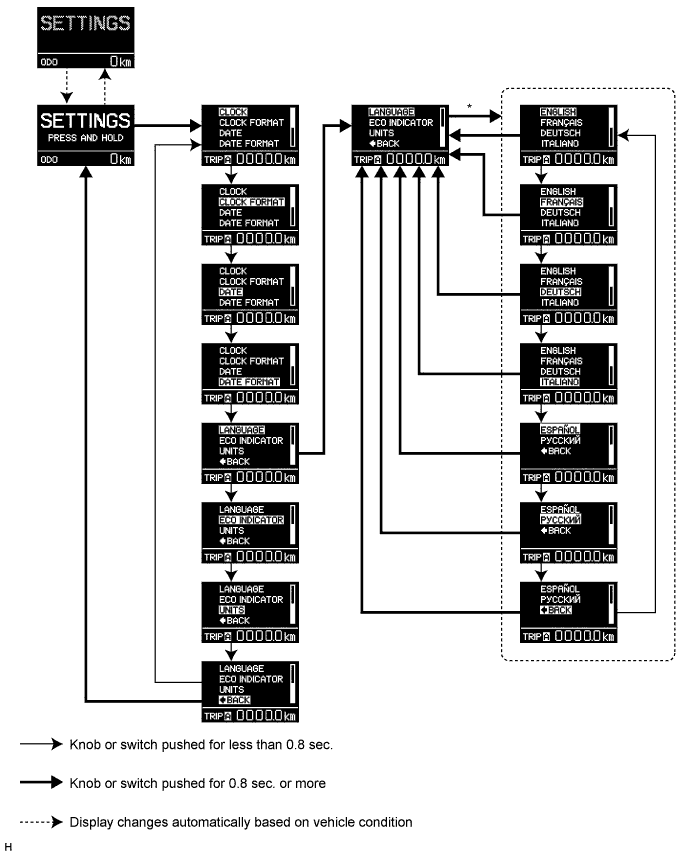
*: Current condition
The screen changes to the current selected item in inverted color character.
Tech Tips
English, French, German, Italian, Spanish or Russian can be displayed.
-