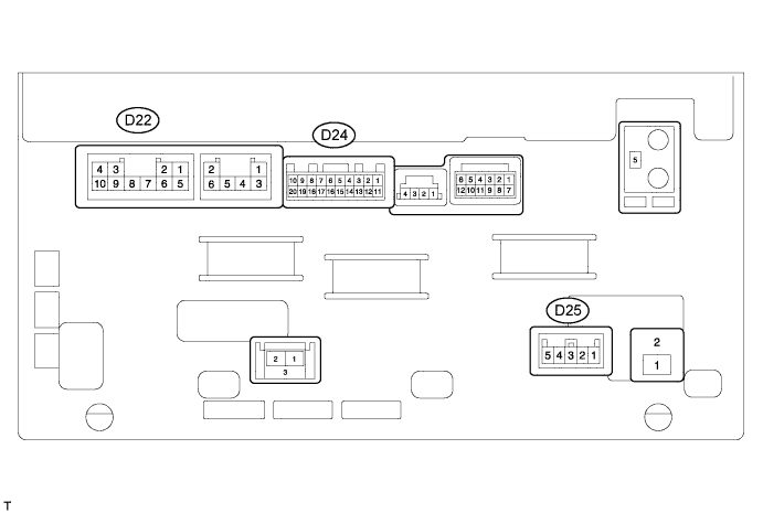
REAR VIEW MONITOR SYSTEM (w/ Navigation System) TERMINALS OF ECU

-
CHECK NAVIGATION RECEIVER ASSEMBLY (for HDD)
-
Disconnect the D22 navigation receiver assembly connector.
-
Measure the voltage and resistance according to the value(s) in the table below.
Terminal No. (Symbol) Wiring Color Terminal Description Condition Specified Condition D22-7 (GND) - Body ground BR - Body ground Ground Always Below 1 Ω D22-4 (B) - D22-7 (GND) SB - BR Battery Always 11 to 14 V If the result is not as specified, there may be a malfunction on the wire harness side.
-
Reconnect the D22 navigation receiver assembly connector.
-
Measure the voltage according to the value(s) in the table below.
Terminal No. (Symbol) Wiring Color Terminal Description Condition Specified Condition D24-2 (CA+) - D24-12 (CGND) B - Shielded Power source Ignition switch ON, shift lever in R 5.5 to 7.05 V D24-12 (CGND) - Body ground Shielded - Body ground Shielding Always Below 1 V D25-5 (REV) - D22-7 (GND) R - BR Reverse signal Ignition switch ON, shift lever in R 11 to 14 V Ignition switch ON, shift lever not in R Below 1 V D24-1 (V+) - D24-11 (V-) R - W Display signal Ignition switch ON, shift lever in R Waveform 1 Ignition switch ON, shift lever in R, screen blacked out by covering camera lens Waveform 2 If the result is not as specified, the navigation receiver assembly may have a malfunction.
-
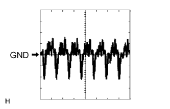
Using an oscilloscope, check waveform 1.
Measurement Condition Item Content Terminal No. (Symbol) D24-1 (V+) - D24-11 (V-) Tool Setting 0.2 V/DIV., 50 μs/DIV. Condition Ignition switch ON, shift lever in R -
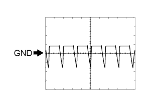
Using an oscilloscope, check waveform 2.
Measurement Condition Item Content Terminal No. (Symbol) D24-1 (V+) - D24-11 (V-) Tool Setting 0.2 V/DIV., 50 μs/DIV. Condition Ignition switch ON, shift lever in R, screen blacked out by covering camera lens
-