REAR VIEW MONITOR SYSTEM (for Radio and Display Type) Display Signal Circuit between Radio and Display Assembly and Television Camera Assembly
DESCRIPTION
The display signal from the rear television camera assembly transmits to the radio and display receiver assembly.
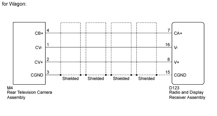
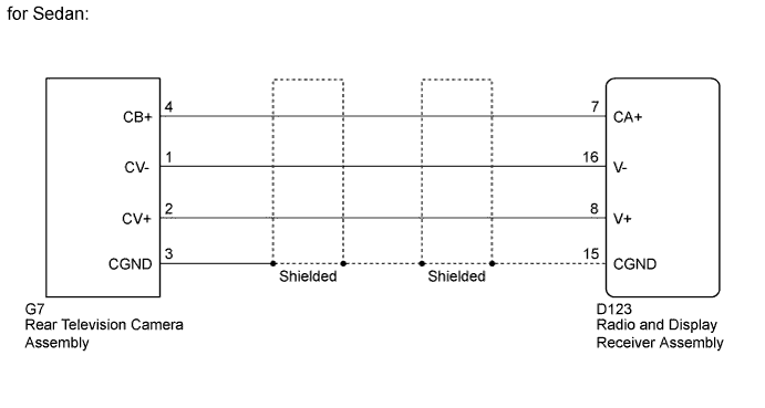
WIRING DIAGRAM
INSPECTION PROCEDURE
PROCEDURE
-
CHECK HARNESS AND CONNECTOR (RADIO AND DISPLAY RECEIVER ASSEMBLY - REAR TELEVISION CAMERA ASSEMBLY)
-
Disconnect the D123 radio and display receiver assembly connector.
-
Disconnect the M4*1 or G7*2 rear television camera assembly connector.
-
*1: for Wagon
-
*2: for Sedan
-
-
Measure the resistance according to the value(s) in the table below.
Standard Resistance for Wagon Tester Connection Condition Specified Condition D123-7 (CA+) - M4-4 (CB+) Always Below 1 Ω D123-8 (V+) - M4-2 (CV+) Always Below 1 Ω D123-15 (CGND) - M4-3 (CGND) Always Below 1 Ω D123-16 (V-) - M4-1 (CV-) Always Below 1 Ω D123-7 (CA+) - Body ground Always 10 kΩ or higher D123-8 (V+) - Body ground Always 10 kΩ or higher D123-15 (CGND) - Body ground Always 10 kΩ or higher D123-16 (V-) - Body ground Always 10 kΩ or higher for Sedan Tester Connection Condition Specified Condition D123-7 (CA+) - G7-4 (CB+) Always Below 1 Ω D123-8 (V+) - G7-2 (CV+) Always Below 1 Ω D123-15 (CGND) - G7-3 (CGND) Always Below 1 Ω D123-16 (V-) - G7-1 (CV-) Always Below 1 Ω D123-7 (CA+) - Body ground Always 10 kΩ or higher D123-8 (V+) - Body ground Always 10 kΩ or higher D123-15 (CGND) - Body ground Always 10 kΩ or higher D123-16 (V-) - Body ground Always 10 kΩ or higher
NG 
REPAIR OR REPLACE HARNESS OR CONNECTOR
OK 
-
-
CHECK RADIO AND DISPLAY RECEIVER ASSEMBLY
-
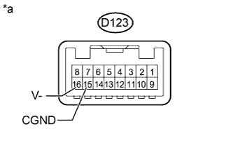
Text in Illustration *a Component without harness connected
(Radio and Display Receiver Assembly)
Disconnect the D123 radio and display receiver assembly connector.
-
Measure the resistance according to the value(s) in the table below.
Standard Resistance Tester Connection Condition Specified Condition D123-16 (V-) - Body ground Always Below 1 Ω D123-15 (CGND) - Body ground Always Below 1 Ω
NG
REPLACE RADIO AND DISPLAY RECEIVER ASSEMBLY Click here
OK
-
-
CHECK RADIO AND DISPLAY RECEIVER ASSEMBLY
-
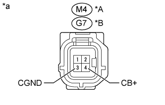
Text in Illustration *A for Wagon *B for Sedan *a Front view of wire harness connector
(to Rear Television Camera Assembly)
Disconnect the M4*1 or G7*2 rear television camera assembly connector.
-
*1: for Wagon
-
*2: for Sedan
-
-
Measure the voltage according to the value(s) in the table below.
Standard Voltage for Wagon Tester Connection Condition Specified Condition M4-4 (CB+) - M4-3 (CGND) Within 60 seconds after turning ignition switch to ACC 5.5 to 7.05 V for Sedan Tester Connection Condition Specified Condition G7-4 (CB+) - G7-3 (CGND) Within 60 seconds after turning ignition switch to ACC 5.5 to 7.05 V
NG
REPLACE RADIO AND DISPLAY RECEIVER ASSEMBLY Click here
OK
-
-
CHECK REAR TELEVISION CAMERA ASSEMBLY
-
Using an oscilloscope, check the waveform.
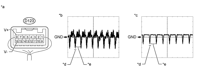
Text in Illustration *a Component with harness connected
(Radio and Display Receiver Assembly)
*b Waveform 1 *c Waveform 2 *d Synchronization Signal *e Video Waveform - - Tech Tips
A waterproof connector is used for the rear television camera assembly. Therefore, inspect the waveform at the radio and display receiver assembly with the connector connected.
Measurement Condition Item Content Terminal No. (Symbol) D123-8 (V+) - D123-16 (V-) Tool Setting 0.2 V/DIV., 50 μs/DIV. Condition
-
Waveform 1: Ignition switch ON, shift lever in R
-
Waveform 2: Ignition switch ON, shift lever in R, screen blacked out by covering camera lens
OK Waveform is as shown in the illustration. Tech Tips
The video waveform changes according to the image sent by the rear television camera assembly.
Result Result Proceed to OK A NG (for Wagon) B NG (for Sedan) C -
B
REPLACE REAR TELEVISION CAMERA ASSEMBLY Click here
C
REPLACE REAR TELEVISION CAMERA ASSEMBLY Click here
A 
PROCEED TO NEXT SUSPECTED AREA SHOWN IN PROBLEM SYMPTOMS TABLE Click here
-