NAVIGATION SYSTEM (for HDD) Speaker Circuit
DESCRIPTION
The navigation receiver assembly and stereo component amplifier assembly send sound signals to the speakers.
WIRING DIAGRAM
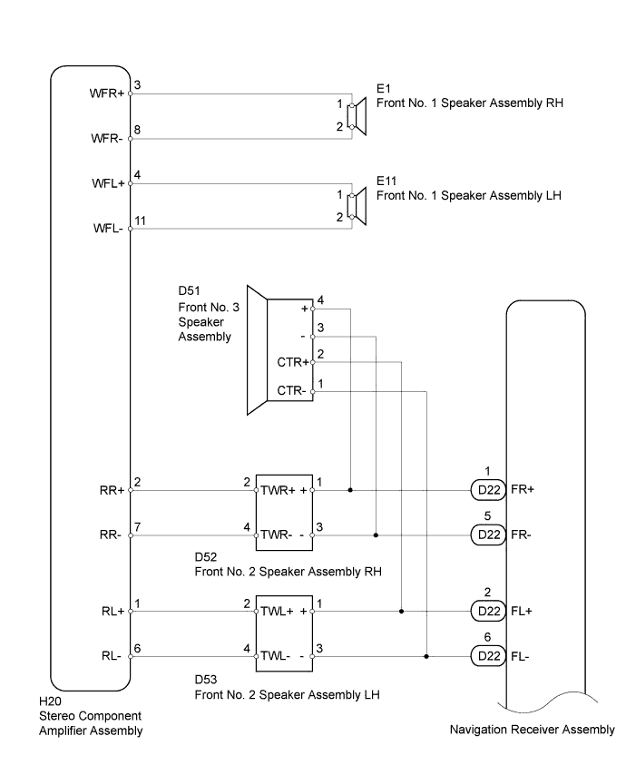
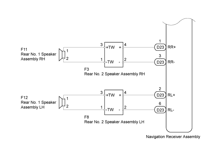
INSPECTION PROCEDURE
PROCEDURE
-
CHECK SPEAKER
-
Check the malfunctioning speakers.
Result Result Proceed to Malfunction in front speaker area A Malfunction in rear speaker area B
B 
CHECK SPEAKER Click here
A 
-
-
CHECK SPEAKER
-
Check the malfunctioning speakers.
Result Result Proceed to Front No. 1 speaker assembly LH/RH A Front No. 2 speaker assembly LH/RH B Front No. 3 speaker assembly C
B
INSPECT FRONT NO. 2 SPEAKER ASSEMBLY Click here
C
INSPECT FRONT NO. 3 SPEAKER ASSEMBLY Click here
A
-
-
INSPECT FRONT NO. 1 SPEAKER ASSEMBLY
-
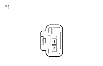
Text in Illustration *1 Component without harness connected
(Front No. 1 Speaker Assembly)
Disconnect the E11*1 and/or E1*2 speaker connector.
*1: for LH
*2: for RH
-
Measure the resistance according to the value(s) in the table below.
Standard Resistance Tester Connection Condition Specified Condition 1 - 2 Always 2 Ω
NG 
REPLACE FRONT NO. 1 SPEAKER ASSEMBLY Click here
OK
-
-
CHECK HARNESS AND CONNECTOR (STEREO COMPONENT AMPLIFIER - FRONT NO. 1 SPEAKER)
-
Disconnect the H20 stereo component amplifier connector.
-
Disconnect the E11*1 and/or E1*2 speaker connector.
*1: for LH
*2: for RH
-
Measure the resistance according to the value(s) in the table below.
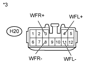
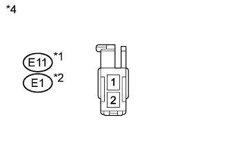
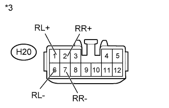
Standard Resistance for LH Tester Connection Condition Specified Condition H20-4 (WFL+) - E11-1 Always Below 1 Ω H20-11 (WFL-) - E11-2 Always Below 1 Ω H20-4 (WFL+) - Body ground Always 10 kΩ or higher H20-11 (WFL-) - Body ground Always 10 kΩ or higher for RH Tester Connection Condition Specified Condition H20-3 (WFR+) - E1-1 Always Below 1 Ω H20-8 (WFR-) - E1-2 Always Below 1 Ω H20-3 (WFR+) - Body ground Always 10 kΩ or higher H20-8 (WFR-) - Body ground Always 10 kΩ or higher Text in Illustration *1 for LH *2 for RH *3 Front view of wire harness connector
(to Stereo Component Amplifier Assembly)
*4 Front view of wire harness connector
(to Front No. 1 Speaker Assembly)
NG
REPAIR OR REPLACE HARNESS OR CONNECTOR
OK
-
-
CHECK HARNESS AND CONNECTOR (STEREO COMPONENT AMPLIFIER - FRONT NO. 2 SPEAKER)
-
Disconnect the H20 stereo component amplifier connector.
-
Disconnect the D53*1 and/or D52*2 speaker connector.
*1: for LH
*2: for RH
-
Measure the resistance according to the value(s) in the table below.
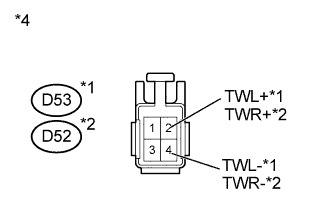
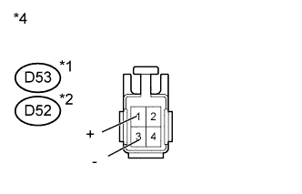
Standard Resistance for LH Tester Connection Condition Specified Condition H20-1 (RL+) - D53-2 (TWL+) Always Below 1 Ω H20-6 (RL-) - D53-4 (TWL-) Always Below 1 Ω H20-1 (RL+) - Body ground Always 10 kΩ or higher H20-6 (RL-) - Body ground Always 10 kΩ or higher for RH Tester Connection Condition Specified Condition H20-2 (RR+) - D52-2 (TWR+) Always Below 1 Ω H20-7 (RR-) - D52-4 (TWR-) Always Below 1 Ω H20-2 (RR+) - Body ground Always 10 kΩ or higher H20-7 (RR-) - Body ground Always 10 kΩ or higher Text in Illustration *1 for LH *2 for RH *3 Front view of wire harness connector
(to Stereo Component Amplifier Assembly)
*4 Front view of wire harness connector
(to Front No. 2 Speaker Assembly)
NG
REPAIR OR REPLACE HARNESS OR CONNECTOR
OK
-
-
INSPECT FRONT NO. 2 SPEAKER ASSEMBLY
-
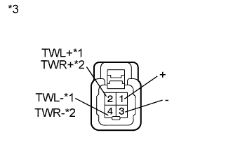
Text in Illustration *1 for LH *2 for RH *3 Component without harness connected
(Front No. 2 Speaker Assembly)
Disconnect the D53*1 and/or D52*2 speaker connector.
*1: for LH
*2: for RH
-
Measure the resistance according to the value(s) in the table below.
Standard Resistance for LH Tester Connection Condition Specified Condition 1 (+) - 2 (TWL+) Always Below 1 Ω 3 (-) - 4 (TWL-) Always Below 1 Ω for RH Tester Connection Condition Specified Condition 1 (+) - 2 (TWR+) Always Below 1 Ω 3 (-) - 4 (TWR-) Always Below 1 Ω
NG
REPLACE FRONT NO. 2 SPEAKER ASSEMBLY Click here
OK 
REPLACE STEREO COMPONENT AMPLIFIER ASSEMBLY Click here
-
-
INSPECT FRONT NO. 2 SPEAKER ASSEMBLY
-
Temporarily replace the speaker with a new or normally functioning one Click here.
-
Check that the malfunction disappears.
Tech Tips
-
Connect all speaker connectors to the speakers.
-
When there is a possibility that either the right or left front speaker is defective, inspect by interchanging the right one with the left one.
Result Result Proceed to Malfunction does not disappear A Malfunction disappears B -
B
REPLACE FRONT NO. 2 SPEAKER ASSEMBLY Click here
A
-
-
CHECK HARNESS AND CONNECTOR (NAVIGATION RECEIVER - FRONT NO. 2 SPEAKER)
-

Disconnect the D22 navigation receiver assembly connector.
-
Disconnect the D53*1 and/or D52*2 speaker connector.
*1: for LH
*2: for RH
-
Measure the resistance according to the value(s) in the table below.
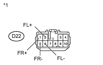
Standard Resistance for LH Tester Connection Condition Specified Condition D22-2 (FL+) - D53-1 (+) Always Below 1 Ω D22-6 (FL-) - D53-3 (-) Always Below 1 Ω D22-2 (FL+) - Body ground Always 10 kΩ or higher D22-6 (FL-) - Body ground Always 10 kΩ or higher for RH Tester Connection Condition Specified Condition D22-1 (FR+) - D52-1 (+) Always Below 1 Ω D22-5 (FR-) - D52-3 (-) Always Below 1 Ω D22-1 (FR+) - Body ground Always 10 kΩ or higher D22-5 (FR-) - Body ground Always 10 kΩ or higher Text in Illustration *1 for LH *2 for RH *3 Front view of wire harness connector
(to Navigation Receiver Assembly)
*4 Front view of wire harness connector
(to Front No. 2 Speaker Assembly)
NG
REPAIR OR REPLACE HARNESS OR CONNECTOR
OK
REPLACE NAVIGATION RECEIVER ASSEMBLY Click here
-
-
INSPECT FRONT NO. 3 SPEAKER ASSEMBLY
-
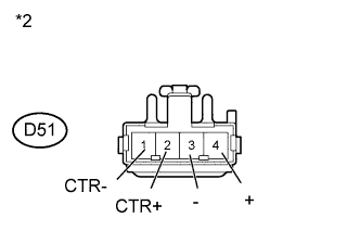
Text in Illustration *1 Component without harness connected
(Front No. 3 Speaker Assembly)
Disconnect the D51 speaker connector.
-
Measure the resistance according to the value(s) in the table below.
Standard Resistance Tester Connection Condition Specified Condition 1 (CTR-) - 2 (CTR+) Always 40 Ω 3 (-) - 4 (+) Always 40 Ω
NG
REPLACE FRONT NO. 3 SPEAKER ASSEMBLY Click here
OK
-
-
CHECK HARNESS AND CONNECTOR (NAVIGATION RECEIVER - FRONT NO. 3 SPEAKER)
-
Disconnect the D22 navigation receiver assembly connector.
-
Disconnect the D51 speaker connector.
-
Measure the resistance according to the value(s) in the table below.
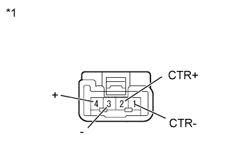
Standard Resistance Tester Connection Condition Specified Condition D22-1 (FR+) - D51-4 (+) Always Below 1 Ω D22-5 (FR-) - D51-3 (-) Always Below 1 Ω D22-2 (FL+) - D51-2 (CTR+) Always Below 1 Ω D22-6 (FL-) - D51-1 (CTR-) Always Below 1 Ω D22-1 (FR+) - Body ground Always 10 kΩ or higher D22-5 (FR-) - Body ground Always 10 kΩ or higher D22-2 (FL+) - Body ground Always 10 kΩ or higher D22-6 (FL-) - Body ground Always 10 kΩ or higher Text in Illustration *1 Front view of wire harness connector
(to Navigation Receiver Assembly)
*2 Front view of wire harness connector
(to Front No. 3 Speaker Assembly)
NG
REPAIR OR REPLACE HARNESS OR CONNECTOR
OK
REPLACE NAVIGATION RECEIVER ASSEMBLY Click here
-
-
CHECK SPEAKER
-
Check the malfunctioning speakers.
Result Result Proceed to Rear No. 1 speaker assembly LH/RH A Rear No. 2 speaker assembly LH/RH B
B
INSPECT REAR NO. 2 SPEAKER ASSEMBLY Click here
A
-
-
INSPECT REAR NO. 1 SPEAKER ASSEMBLY
-

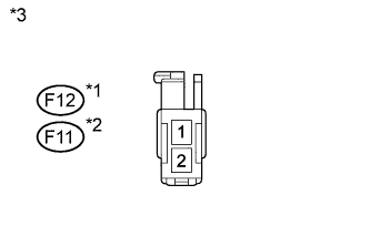
Text in Illustration *1 Component without harness connected
(Rear No. 1 Speaker Assembly)
Disconnect the F12*1 and/or F11*2 speaker connector.
*1: for LH
*2: for RH
-
Measure the resistance according to the value(s) in the table below.
Standard Resistance Tester Connection Condition Specified Condition 1 - 2 Always 4.0 Ω
NG
REPLACE REAR NO. 1 SPEAKER ASSEMBLY Click here
OK
-
-
CHECK HARNESS AND CONNECTOR (REAR NO. 1 SPEAKER - REAR NO. 2 SPEAKER)
*1: for LH
*2: for RH
-
Disconnect the F12*1 and/or F11*2 speaker connector.
-
Disconnect the F8*1 and/or F3*2 speaker connector.
-
Measure the resistance according to the value(s) in the table below.
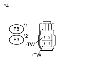
Standard Resistance for LH Tester Connection Condition Specified Condition F12-1 - F8-3 (+TW) Always Below 1 Ω F12-2 - F8-1 (-TW) Always Below 1 Ω F12-1 - Body ground Always 10 kΩ or higher F12-2 - Body ground Always 10 kΩ or higher for RH Tester Connection Condition Specified Condition F11-1 - F3-3 (+TW) Always Below 1 Ω F11-2 - F3-1 (-TW) Always Below 1 Ω F11-1 - Body ground Always 10 kΩ or higher F11-2 - Body ground Always 10 kΩ or higher Text in Illustration *1 for LH *2 for RH *3 Front view of wire harness connector
(to Rear No. 1 Speaker Assembly)
*4 Front view of wire harness connector
(to Rear No. 2 Speaker Assembly)
NG
REPAIR OR REPLACE HARNESS OR CONNECTOR
OK
REPLACE REAR NO. 2 SPEAKER ASSEMBLY Click here
-
-
INSPECT REAR NO. 2 SPEAKER ASSEMBLY
-
Temporarily replace the speaker with a new or normally functioning one Click here.
-
Check that the malfunction disappears.
Tech Tips
-
Connect all speaker connectors to the speakers.
-
When there is a possibility that either the right or left front speaker is defective, inspect by interchanging the right one with the left one.
Result Result Proceed to Malfunction does not appears A Malfunction disappears B -
B
REPLACE REAR NO. 2 SPEAKER ASSEMBLY Click here
A
-
-
CHECK HARNESS AND CONNECTOR (NAVIGATION RECEIVER - REAR NO. 2 SPEAKER)
-
Disconnect the D23 navigation receiver assembly connector.
-
Disconnect the F8*1 and/or F3*2 speaker connector.
*1: for LH
*2: for RH
-
Measure the resistance according to the value(s) in the table below.
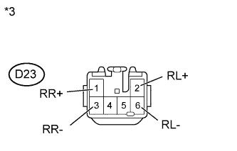
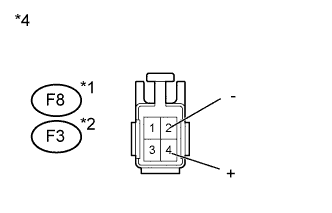
Standard Resistance for LH Tester Connection Condition Specified Condition D23-2 (RL+) - F8-4 (+) Always Below 1 Ω D23-6 (RL-) - F8-2 (-) Always Below 1 Ω D23-2 (RL+) - Body ground Always 10 kΩ or higher D23-6 (RL-) - Body ground Always 10 kΩ or higher for RH Tester Connection Condition Specified Condition D23-1 (RR+) - F3-4 (+) Always Below 1 Ω D23-3 (RR-) - F3-2 (-) Always Below 1 Ω D23-1 (RR+) - Body ground Always 10 kΩ or higher D23-3 (RR-) - Body ground Always 10 kΩ or higher Text in Illustration *1 for LH *2 for RH *3 Front view of wire harness connector
(to Navigation Receiver Assembly)
*4 Front view of wire harness connector
(to Rear No. 2 Speaker Assembly)
NG
REPAIR OR REPLACE HARNESS OR CONNECTOR
OK
REPLACE NAVIGATION RECEIVER ASSEMBLY Click here
-