NAVIGATION SYSTEM TERMINALS OF ECU

-
RADIO AND DISPLAY RECEIVER ASSEMBLY
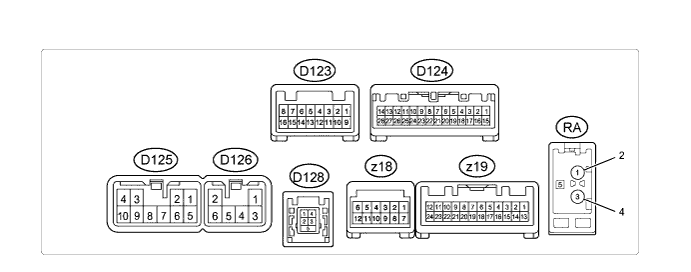
Terminal No. (Symbol) Wiring Color Terminal Description Condition Specified Condition D124-1 (IG) - D125-7 (GND1) G - BR Power source (IG) Ignition switch off Below 1 V Ignition switch ON 11 to 14 V D124-2 (REV) - D125-7 (GND1) R - BR Reverse signal Ignition switch ON, shift lever in R 7.5 to 14 V Ignition switch ON, shift lever not in R Below 1 V D124-4 (MACC) - D125-7 (GND1) B - BR Microphone power supply Ignition switch off Below 1 V Ignition switch ACC 4 to 6 V D124-5 (MIN+) - D125-7 (GND1) W - BR Microphone voice signal See "Microphone Level Test" in Operation Check Click here
- D124-6 (SNS2) - D125-7 (GND1) L - BR Microphone connection detection signal Always Below 1 V D124-9 (CANH) SB CAN communication signal - - D124-10 (CANL) W CAN communication signal - - D124-11 (AGND) - Body ground Shielded - Body ground Shield ground Always Below 1 V D124-17 (SPD) - D125-7 (GND1) Y - BR Vehicle speed signal See "Vehicle Signal Check Mode" in Operation Check Click here
- D124-18 (SGND) - Body ground Shielded - Body ground Shield ground Always Below 1 Ω D124-19 (MIN-) - D125-7 (GND1) R - BR Microphone voice signal See "Microphone Level Test" in Operation Check Click here
- D124-20 (LRHD) - Body ground W-B -Body ground Ground Always Below 1 V D124-21 (SW1) - D125-7 (GND1) P - BR Steering pad switch signal Steering pad switch not operated 2.97 to 3.56 V SEEK+ switch pushed 0.27 to 0.35 V SEEK- switch pushed 0.86 to 1.03 V VOL+ switch pushed 1.51 to 1.79 V VOL- switch pushed 2.22 to 2.66 V D124-22 (SW2) - D125-7 (GND1) SB - BR Steering pad switch signal Steering pad switch not operated 2.97 to 3.56 V MODE switch pushed 0.27 to 0.35 V On hook switch pushed 0.86 to 1.03 V Off hook switch pushed 1.51 to 1.79 V Voice switch pushed 2.22 to 2.66 V D124-23 (SWG) - D125-7 (GND1) V - BR Steering pad switch ground Always Below 1 Ω D124-25 (ADPG) - D125-7 (GND1) L - BR External device connection detection signal External device connected Below 1 V D124-26 (VAR+) - D125-7 (GND1) R - BR Sound signal (Right) External device playing (When stereo jack used) A waveform synchronized with sound is output D124-27 (VA-) - D125-7 (GND1) W - BR Ground Always Below 1 Ω D124-28 (VAL+) - D125-7 (GND1) B - BR Sound signal (Left) External device playing (When stereo jack used) A waveform synchronized with sound is output D125-1 (FR+) - D125-7 (GND1) LG - BR Sound signal (Front Right) Audio system playing A waveform synchronized with sound is output D125-2 (FL+) - D125-7 (GND1) P - BR Sound signal (Front Left) Audio system playing A waveform synchronized with sound is output D125-3 (ACC1) - D125-7 (GND1) GR - BR Power source (ACC) Ignition switch off Below 1 V Ignition switch ACC 11 to 14 V D125-4 (+B1) - D125-7 (GND1) SB - BR Power source (+B) Always 11 to 14 V D125-5 (FR-) - D125-7 (GND1) L - BR Sound signal (Front Right) Audio system playing A waveform synchronized with sound is output D125-6 (FL-) - D125-7 (GND1) V - BR Sound signal (Front Left) Audio system playing A waveform synchronized with sound is output D125-7 (GND1) - Body ground BR - Body ground Ground Always Below 1 Ω D125-9 (AMP) - D125-7 (GND1)* BR - BR Power source of stereo component amplifier Audio system playing 11 to 14 V D125-10 (ILL+) - D125-7 (GND1) G - BR Illumination signal Light control switch off Below 1 V Light control switch in tail or head position 11 to 14 V D126-1 (RR+) - D125-7 (GND1) R - BR Sound signal (Rear Right) Audio system playing A waveform synchronized with sound is output D126-2 (RL+) - D125-7 (GND1) B - BR Sound signal (Rear Left) Audio system playing A waveform synchronized with sound is output D126-3 (RR-) - D125-7 (GND1) W - BR Sound signal (Rear Right) Audio system playing A waveform synchronized with sound is output D126-6 (RL-) - D125-7 (GND1) Y - BR Sound signal (Rear Left) Audio system playing A waveform synchronized with sound is output D128-1 - D128-4 # - # Battery Always 4.5 to 5.5 V D128-2 - D128-4 # - # Data signal USB device or "iPod" connected - D128-3 - D128-4 # - # Data signal USB device or "iPod" connected - D128-4 - Body ground # - Body ground Ground Always Below 1 Ω RA-5 (ANT+) - D125-7 (GND1) B - BR Power source of antenna Ignition switch ACC
Radio switch on and FM or AM selected
11 to 14 V z18-2 (CDR+) - D125-7 (GND1) L - BR Sound signal (Right) Audio system playing A waveform synchronized with sound is output z18-3 (CDR-) - D125-7 (GND1) LG - BR Sound signal (Right) Audio system playing A waveform synchronized with sound is output z18-4 (CDL+) - D125-7 (GND1) BR - BR Sound signal (Left) Audio system playing A waveform synchronized with sound is output z18-5 (CDL-) - D125-7 (GND1) G - BR Sound signal (Left) Audio system playing A waveform synchronized with sound is output z18-6 (MUTE) - D125-7 (GND1) B - BR Mute signal Audio system playing Above 3.5 V Audio system changing mode Below 1 V z18-9 (TX+) BR AVC-LAN communication signal - - z18-10 (TX-) W-B AVC-LAN communication signal - - z19-1 (+B2) - D125-7 (GND1) B - BR Power source Always 11 to 14 V z19-2 (SPDO) - D125-7 (GND1) G - BR Vehicle speed signal See "Vehicle Signal Check Mode" in Operation Check Click here
- z19-5 (REVO) - D125-7 (GND1) L - BR Reverse signal See "Vehicle Signal Check Mode" in Operation Check Click here
- z19-6 (VSYN) Y Display signal - - z19-7 (HSYN) P Display signal - - z19-8 (AGND) - D125-7 (GND1) LG - BR Ground Always Below 1 Ω z19-10 (B) W Display signal - - z19-11 (G) R Display signal - - z19-12 (R) V Display signal - - z19-13 (ACC2) - D125-7 (GND1) P - BR Power source (ACC) Ignition switch off Below 1 V Ignition switch ACC 11 to 14 V z19-14 (GND2) - Body ground W-B - Body ground Ground Always Below 1 Ω z19-19 (MIC+) - D125-7 (GND1) R - BR Microphone voice signal See "Microphone Level Test" in Operation Check Click here
- z19-20 (MIC-) - D125-7 (GND1) V - BR Microphone voice signal See "Microphone Level Test" in Operation Check Click here
- z19-22 (VOL+) - D125-7 (GND1) Y - BR Voice signal Voice guidance sounding A waveform synchronized with sound is output z19-23 (VOL-) - D125-7 (GND1) W - BR Voice signal Voice guidance sounding A waveform synchronized with sound is output
-
#: There is no wire color information.
-
*: for 11 Speakers
-
-
EXTENSION MODULE
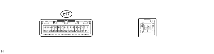
Terminal No. (Symbol) Wiring Color Terminal Description Condition Specified Condition z17-1 (MUTE) - z17-32 (GND2) B - W-B Mute signal Mute off Above 3.5 V Mute on Below 1 V z17-2 (TX+) BR AVC-LAN communication signal - - z17-3 (TX-) W-B AVC-LAN communication signal - - z17-5 (VSYN) Y Display signal - - z17-6 (B) W Display signal - - z17-7 (R) V Display signal - - z17-9 (MIC+) - z17-32 (GND2) R - W-B Microphone voice signal See "Microphone Level Test" in Operation Check Click here
- z17-11 (ACC2) - z17-32 (GND2) P - W-B Power source (ACC) Ignition switch off Below 1 V Ignition switch ACC 11 to 14 V z17-12 (CDR-) - z17-32 (GND2) LG - W-B Sound signal (Right) Audio system playing A waveform synchronized with sound is output z17-13 (CDR+) - z17-32 (GND2) L - W-B Sound signal (Right) Audio system playing A waveform synchronized with sound is output z17-14 (CDL-) - z17-32 (GND2) G - W-B Sound signal (Left) Audio system playing A waveform synchronized with sound is output z17-15 (CDL+) - z17-32 (GND2) BR - W-B Sound signal (Left) Audio system playing A waveform synchronized with sound is output z17-16 (+B2) - z17-32 (GND2) B - W-B Power source (+B) Always 11 to 14 V z17-18 (SPDO) - z17-32 (GND2) G - W-B Vehicle speed signal Ignition switch ON
Drive wheel turned slowly
Pulse generation z17-19 (REVO) - z17-32 (GND2) L - W-B Reverse signal See "Vehicle Signal Check Mode" in Operation Check Click here
- z17-20 (AGND) - z17-32 (GND2) LG - W-B Ground Always Below 1 Ω z17-22 (HSYN) P Display signal - - z17-23 (G) R Display signal - - z17-25 (MIC-) - z17-32 (GND) V - W-B Microphone voice signal See "Microphone Level Test" in Operation Check Click here
- z17-30 (VOI-) - z17-32 (GND) W - W-B Voice signal Voice guidance sounding A waveform synchronized with sound is output z17-31 (VOI+) - z17-32 (GND) Y - W-B Voice signal Voice guidance sounding A waveform synchronized with sound is output z17-32 (GND2) - Body ground W-B - Body ground Ground Always Below 1 Ω -
STEREO COMPONENT AMPLIFIER ASSEMBLY (for 11 Speakers)
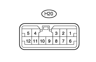
Terminal No. (Symbol) Wiring Color Terminal Description Condition Specified Condition H20-1 (RL+) - H20-10 (GND) P - W-B Sound signal (Front Left) Audio system playing A waveform synchronized with sound is output H20-2 (RR+) - H20-10 (GND) LG - W-B Sound signal (Front Right) Audio system playing A waveform synchronized with sound is output H20-3 (WFR+) - H20-10 (GND) LG - W-B Sound signal (Front Right) Audio system playing A waveform synchronized with sound is output H20-4 (WFL+) - H20-10 (GND) P - W-B Sound signal (Front Left) Audio system playing A waveform synchronized with sound is output H20-5 (+B) - H20-10 (GND) G - W-B Power source (+B) Always 11 to 14 V H20-6 (RL-) - H20-10 (GND) V - W-B Sound signal (Front Left) Audio system playing A waveform synchronized with sound is output H20-7 (RR-) - H20-10 (GND) L - W-B Sound signal (Front Right) Audio system playing A waveform synchronized with sound is output H20-8 (WFR-) - H20-10 (GND) L - W-B Sound signal (Front Right) Audio system playing A waveform synchronized with sound is output H20-9 (AMP+) - Body ground BR - Body ground Power source of stereo component amplifier Audio system playing 11 to 14 V H20-10 (GND) - Body ground W-B - Body ground Ground Always Below 1 Ω H20-11 (WFL-) - H20-10 (GND) V - W-B Sound signal (Front Left) Audio system playing A waveform synchronized with sound is output H20-12 (ACC) - H20-10 (GND) GR - W-B Power source (ACC) Ignition switch off Below 1 V Ignition switch ACC 11 to 14 V