RADIO RECEIVER INSTALLATION

-
INSTALL NO. 2 RADIO BRACKET (for Radio Receiver Type)
-
Install the No. 2 radio bracket with the 3 screws.
- Torque:
- 4.0 N*m { 40 kgf*cm, 35 in.*lbf }
-
-
INSTALL NO. 2 RADIO RECEIVER BRACKET (for Radio and Display Type)
-
Install the No. 2 radio receiver bracket with the 3 screws.
- Torque:
- 4.0 N*m { 40 kgf*cm, 35 in.*lbf }
-
-
INSTALL NO. 1 RADIO BRACKET (for Radio Receiver Type)
-
Install the No. 1 radio bracket with the 3 screws.
- Torque:
- 4.0 N*m { 40 kgf*cm, 35 in.*lbf }
-
-
INSTALL NO. 1 RADIO RECEIVER BRACKET (for Radio and Display Type)
-
Install the No. 1 radio receiver bracket with the 3 screws.
- Torque:
- 4.0 N*m { 40 kgf*cm, 35 in.*lbf }
-
-
INSTALL RADIO RECEIVER ASSEMBLY WITH BRACKET (for Radio Receiver Type)
-
Connect the connectors.
-
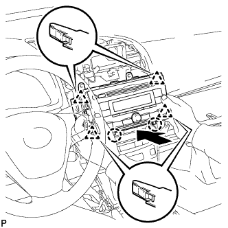
Insert the radio receiver assembly with bracket to attach the 4 clips and 2 claws on its backside.
Note
When inserting the radio receiver, do not press the knobs on it.
-
Install the radio receiver assembly with bracket with the 4 screws.
- Torque:
- 4.0 N*m { 40 kgf*cm, 35 in.*lbf }
-
-
INSTALL RADIO AND DISPLAY RECEIVER ASSEMBLY WITH BRACKET (for Radio and Display Type)
-
Connect the connectors.
-
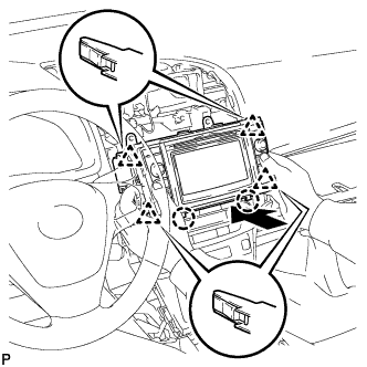
Insert the radio and display receiver assembly with bracket to attach the 4 clips and 2 claws on its backside.
Note
When inserting the radio and display receiver, do not press the knobs on it.
-
Install the radio and display receiver assembly with bracket with the 4 screws.
- Torque:
- 4.0 N*m { 40 kgf*cm, 35 in.*lbf }
-
-
INSTALL CENTER INSTRUMENT PANEL REGISTER ASSEMBLY WITH FINISH PANEL
-
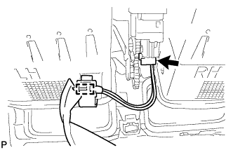
Connect the connector and clamp.
-
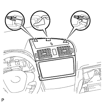
Attach the 2 clips and hook.
-
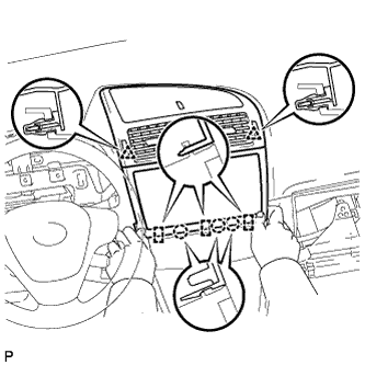
Attach the 2 clips.
-
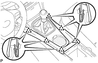
Attach the 3 claws and 3 hooks to install the panel register.
-
-
INSTALL NO. 3 BOX PANEL (w/ Console Box Lid)
-
When replacing the No. 3 box panel with a new one:
-
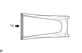
Text in Illustration *1 Cut Cut off the rib (the piece used to maintain the shape of the panel) shown in the illustration.
-
-
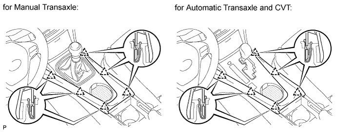
Attach the 6 clips to install the box panel.
-
-
INSTALL NO. 3 BOX PANEL (w/o Console Box Lid)
-
When replacing the No. 3 box panel with a new one:
-
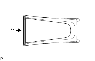
Text in Illustration *1 Cut Cut off the rib (the piece used to maintain the shape of the panel) shown in the illustration.
-
-
Attach the 6 clips to install the box panel.
-
-
INSTALL INSTRUMENT PANEL FINISH PANEL END RH (for LHD)
-
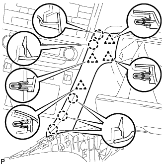
Attach the 4 clips and 5 claws to install the panel end.
-
-
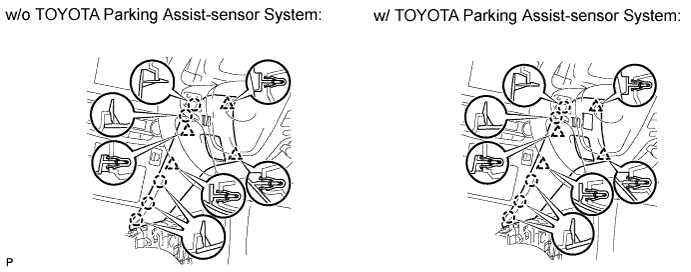
INSTALL INSTRUMENT PANEL FINISH PANEL END RH (for RHD)
-
w/o TOYOTA Parking Assist-sensor System:
-
Attach the 4 clips and 5 claws to install the panel end.
-
-
w/ TOYOTA Parking Assist-sensor System:
-
Connect the connector.
-
Attach the 4 clips and 5 claws to install the panel end.
-
-
-
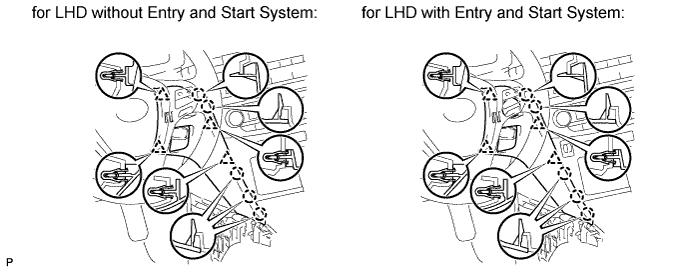
INSTALL INSTRUMENT PANEL FINISH PANEL END LH
-
Attach the 4 clips and 5 claws to install the panel end.
-
-
INSTALL LOWER NO. 1 INSTRUMENT PANEL FINISH PANEL
-
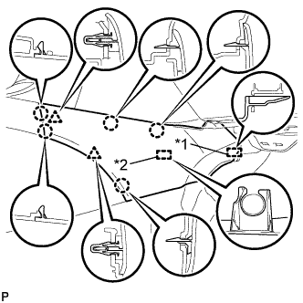
Text in Illustration *1 Guide *2 Clamp Attach the guide near the front of the vehicle.
-
Attach the clamp.
-
Attach the 2 clips and 5 claws to install the finish panel.
-
-
INSTALL LOWER NO. 2 INSTRUMENT PANEL FINISH PANEL
-
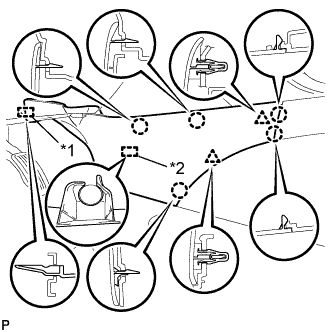
Text in Illustration *1 Guide *2 Clamp Attach the guide near the front of the vehicle.
-
Attach the clamp.
-
Attach the 2 clips and 5 claws to install the finish panel.
-
-
CONNECT CABLE TO NEGATIVE BATTERY TERMINAL
Note
When disconnecting the cable, some systems need to be initialized after the cable is reconnected Click here.