AUDIO AND VISUAL SYSTEM (for Radio and Display Type) TERMINALS OF ECU

-
RADIO AND DISPLAY RECEIVER ASSEMBLY
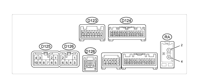
Terminal No. (Symbol) Wiring Color Terminal Description Condition Specified Condition D125-1 (FR+) - D125-7 (GND1) LG - BR Sound signal (Front Right) Audio system playing A waveform synchronized with sound is output D125-2 (FL+) - D125-7 (GND1) P - BR Sound signal (Front Left) Audio system playing A waveform synchronized with sound is output D125-3 (ACC1) - D125-7 (GND1) GR - BR Power source (ACC) Ignition switch off Below 1 V Ignition switch ACC 11 to 14 V D125-4 (+B1) - D125-7 (GND1) SB - BR Power source (+B) Always 11 to 14 V D125-5 (FR-) - D125-7 (GND1) L - BR Sound signal (Front Right) Audio system playing A waveform synchronized with sound is output D125-6 (FL-) - D125-7 (GND1) V - BR Sound signal (Front Left) Audio system playing A waveform synchronized with sound is output D125-7 (GND1) - Body ground BR - Body ground Ground Always Below 1 Ω D125-9 (AMP) - D125-7 (GND1)*1 BR - BR Power source of stereo component amplifier Audio system playing 11 to 14 V D125-10 (ILL+) - D125-7 (GND1) G - BR Illumination signal Light control switch off Below 1 V Light control switch in tail or head position 11 to 14 V D126-1 (RR+) - D125-7 (GND1) R - BR Sound signal (Rear Right) Audio system playing A waveform synchronized with sound is output D126-2 (RL+) - D125-7 (GND1) B - BR Sound signal (Rear Left) Audio system playing A waveform synchronized with sound is output D126-3 (RR-) - D125-7 (GND1) W - BR Sound signal (Rear Right) Audio system playing A waveform synchronized with sound is output D126-6 (RL-) - D125-7 (GND1) Y - BR Sound signal (Rear Left) Audio system playing A waveform synchronized with sound is output D124-1 (IG) - D125-7 (GND1) G - BR Power source (IG) Ignition switch off Below 1 V Ignition switch ON 11 to 14 V D124-2 (REV) - D125-7 (GND1) R - BR Reverse signal See "Vehicle Signal Check Mode" in Operation Check Click here
- D124-4 (MACC) - D125-7 (GND1) B - BR Microphone power supply Ignition switch off Below 1 V Ignition switch ACC 4 to 6 V D124-5 (MIN+) - D125-7 (GND1) W - BR Microphone voice signal See "Microphone Level Test" in Operation Check Click here
- D124-6 (SNS2) - D125-7 (GND1) L - BR Microphone connection detection signal Always Below 1 V D124-9 (CANH) BE CAN communication signal - - D124-10 (CANL) W CAN communication signal - - D124-11 (AGND) - Body ground Shielded - Body ground Shield ground Always Below 1 Ω D124-17 (SPD) - D125-7 (GND1) Y - BR Vehicle speed signal See "Vehicle Signal Check Mode" in Operation Check Click here
- D124-18 (SGND) - Body ground Shielded - Body ground Shield ground Always Below 1 Ω D124-19 (MIN-) - D125-7 (GND1) R - BR Microphone voice signal See "Microphone Level Test" in Operation Check Click here
- D124-20 (LRHD) - Body ground*2 W-B -Body ground Ground Always Below 1 Ω D124-21 (SW1) - D125-7 (GND1) P - BR Steering pad switch signal Steering pad switch not operated 3.3 V or higher SEEK+ switch pushed Below 0.6 V SEEK- switch pushed Approx. 0.9 V VOL+ switch pushed Approx. 1.5 V VOL- switch pushed Approx. 2.4 V D124-22 (SW2) - D125-7 (GND1) SB - BR Steering pad switch signal Steering pad switch not operated 3.3 V or higher MODE switch pushed Below 0.6 V On hook switch pushed Approx. 0.9 V Off hook switch pushed Approx. 1.5 V D124-23 (SWG) - D125-7 (GND1) V - BR Steering pad switch ground Always Below 1 Ω D124-25 (ADPG) - D125-7 (GND1) L - BR External device connection detection signal External device connected Below 1 V D124-26 (VAR+) - D125-7 (GND1) R - BR Sound signal (Right) External device playing (When stereo jack used) A waveform synchronized with sound is output D124-27 (VA-) - D125-7 (GND1) W - BR Ground Always Below 1 Ω D124-28 (VAL+) - D125-7 (GND1) B - BR Sound signal (Left) External device playing (When stereo jack used) A waveform synchronized with sound is output D123-7 (CA+) - D125-7 (GND1)*3 B - BR Television camera power supply Ignition switch ON
Shift lever in R
5.5 to 7.05 V D123-8 (V+) - D125-7 (GND1)*3 R - BR Television camera image signal Ignition switch ON
Shift lever in R
Pulse generation
(Refer to waveform 1)
Ignition switch ON
Shift lever in R, screen blacked out by covering camera lens
Pulse generation
(Refer to waveform 2)
D123-15 (CGND) - Body ground Shielded - Body ground Shield ground Always Below 1 Ω D123-16 (V-) - D125-7 (GND1) W - BR Ground Always Below 1 Ω D128-1 - D128-4 # - # Battery Always 4.5 to 5.5 V D128-2 - D128-4 # - # Data signal USB device or "iPod" connected - D128-3 - D128-4 # - # Data signal USB device or "iPod" connected - D128-4 - Body ground # - # Ground Always Below 1 Ω RA-5 (ANT+) - Body ground # - Body ground Power source of antenna Ignition switch ACC
Radio switch on and FM or AM selected
11 to 14 V
-
#: There is no wire color information.
-
*1: for 11 Speakers
-
*2: for RHD
-
*3: w/ Rear View Monitor System
-
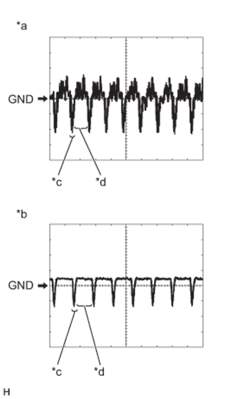
Text in Illustration *a Waveform 1 *b Waveform 2 *c Synchronization Signal *d Video Waveform Reference (Oscilloscope waveform):
-
Waveform 1
Item Content Measurement terminal D123-8 (V+) - D125-7 (GND1) Measurement setting 0.2 V/DIV., 50 μs./DIV. Condition Ignition switch ON, shift lever in R Tech Tips
The video waveform changes according to the image sent by the television camera assembly.
-
Waveform 2
Item Content Measurement terminal D123-8 (V+) - D125-7 (GND1) Measurement setting 0.2 V/DIV., 50 μs./DIV. Condition Ignition switch ON, shift lever in R, screen blacked out by covering camera lens Tech Tips
The video waveform changes according to the image sent by the rear television camera assembly.
-
-
-
STEREO COMPONENT AMPLIFIER ASSEMBLY (for 11 Speakers)
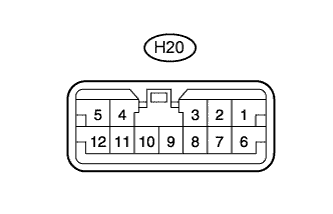
Terminal No. (Symbol) Wiring Color Terminal Description Condition Specified Condition H20-1 (RL+) - H20-10 (GND) P - W-B Sound signal (Front Left) Audio system playing A waveform synchronized with sound is output H20-2 (RR+) - H20-10 (GND) LG - W-B Sound signal (Front Right) Audio system playing A waveform synchronized with sound is output H20-3 (WFR+) - H20-10 (GND) LG - W-B Sound signal (Front Right) Audio system playing A waveform synchronized with sound is output H20-4 (WFL+) - H20-10 (GND) P - W-B Sound signal (Front Left) Audio system playing A waveform synchronized with sound is output H20-5 (+B) - H20-10 (GND) G - W-B Power source (+B) Always 11 to 14 V H20-6 (RL-) - H20-10 (GND) V - W-B Sound signal (Front Left) Audio system playing A waveform synchronized with sound is output H20-7 (RR-) - H20-10 (GND) L - W-B Sound signal (Front Right) Audio system playing A waveform synchronized with sound is output H20-8 (WFR-) - H20-10 (GND) L - W-B Sound signal (Front Right) Audio system playing A waveform synchronized with sound is output H20-9 (AMP+) - Body ground BR - Body ground Power source of stereo component amplifier Audio system playing 11 to 14 V H20-10 (GND) - Body ground W-B - Body ground Ground Always Below 1 V H20-11 (WFL-) - H20-10 (GND) V - W-B Sound signal (Front Left) Audio system playing A waveform synchronized with sound is output H20-12 (ACC) - H20-10 (GND) GR - W-B Power source (ACC) Ignition switch off Below 1 V Ignition switch ACC 11 to 14 V