STEERING GEAR REMOVAL

-
PLACE FRONT WHEELS FACING STRAIGHT AHEAD
-
SECURE STEERING WHEEL
-
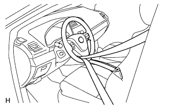
Secure the steering wheel with the seat belt in order to prevent rotation.
Tech Tips
This operation is useful to prevent damage to the spiral cable.
-
-
REMOVE COLUMN HOLE COVER SILENCER SHEET
-
Fold back the floor carpet, and then remove the 2 clips and then column hole cover silencer sheet.
-
-
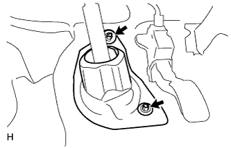
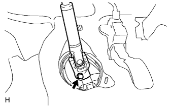
DISCONNECT NO. 2 STEERING INTERMEDIATE SHAFT ASSEMBLY
-
Remove the bolt.
Note
Do not disconnect the No. 2 steering intermediate shaft assembly from the steering intermediate shaft.
-
Text in Illustration *1 Matchmark Put matchmarks on the No. 2 steering intermediate shaft assembly and steering intermediate shaft.
-
Disconnect the No. 2 steering intermediate shaft assembly from the steering intermediate shaft.
-
-
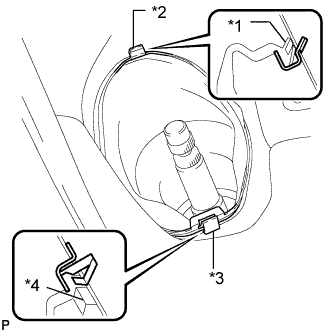
DISCONNECT NO. 1 STEERING COLUMN HOLE COVER SUB-ASSEMBLY
-
Remove clip A and the No. 1 steering column hole cover and detach clip B from the body.
Note
Do not damage clip A or B.
Text in Illustration *1 Lip *2 Clip B *3 Clip A *4 Lip
-
-
REMOVE FRONT WHEELS
-
REMOVE FRONT BUMPER ABSORBER LOWER
-
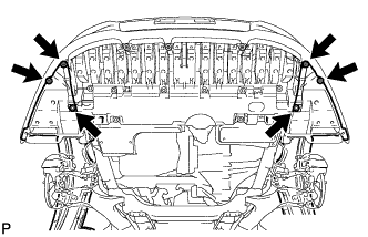
Remove the 4 screws and 2 bolts.
Tech Tips
Pull down the fender liner so that the front lower bumper absorber can be removed in the next step.
-
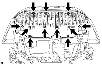
Remove the 3 screws, 8 bolts and front lower bumper absorber.
-
-
REMOVE NO. 1 ENGINE UNDER COVER (for 1AZ-FE)
-
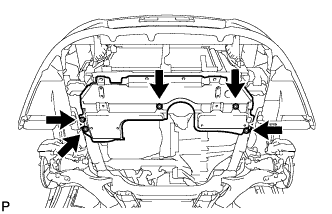
Remove the 5 clips and under cover.
-
-
REMOVE NO. 1 ENGINE UNDER COVER (for ZR Series Engine)
-
Remove the 10 clips and under cover.
-
-
REMOVE NO. 2 ENGINE UNDER COVER (for ZR Series Engine)
-
Remove the 4 clips and under cover.
-
-
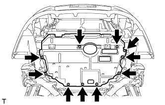
REMOVE CENTER NO. 4 ENGINE UNDER COVER
-
Remove the 5 clips and under cover.
-
-
REMOVE REAR ENGINE UNDER COVER RH
-
Remove the 5 clips and under cover.
-
-
REMOVE REAR ENGINE UNDER COVER LH (for ZR Series Engine)
-
Remove the 5 clips and under cover.
-
-
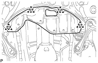
REMOVE FRONT SUSPENSION MEMBER REINFORCEMENT LH
-
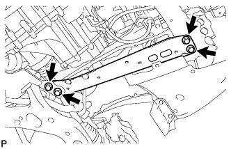
Remove the 4 bolts and front suspension member reinforcement LH.
-
-
REMOVE FRONT SUSPENSION MEMBER REINFORCEMENT RH
-
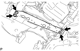
Remove the 4 bolts and front suspension member reinforcement RH.
-
-
DISCONNECT FRONT STABILIZER LINK ASSEMBLY LH
-
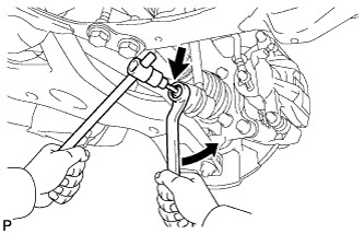
Remove the nut and disconnect the stabilizer link assembly LH from the front stabilizer bar.
Tech Tips
If the ball joint turns together with the nut, use a 6 mm hexagon wrench to hold the stud bolt.
-
-
DISCONNECT FRONT STABILIZER LINK ASSEMBLY RH
Tech Tips
Use the same procedures described for the LH side.
-
DISCONNECT TIE ROD END SUB-ASSEMBLY LH
-
Remove the cotter pin and nut.
-
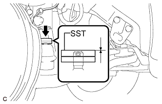
Install SST to the tie rod end.
- SST
- 09960-20010 ( 09961-02060 )
Note
Make sure that the top of SST aligns with the top of the tie rod end.
-
Using SST, separate the tie rod end from the steering knuckle.
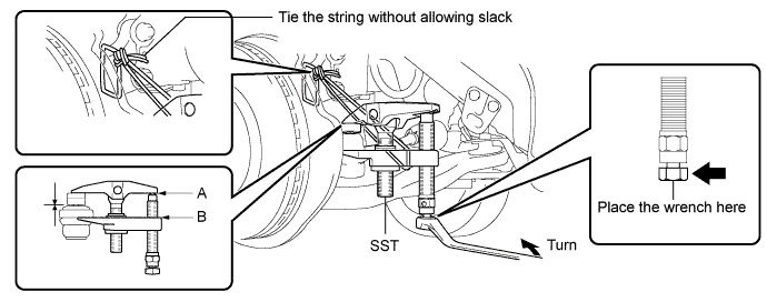
- SST
- 09960-20010 ( 09961-02010 )
Note
Apply grease to the bolt threads and the tip of SST.
Note
-
Be sure to tighten the string firmly to secure SST to the steering knuckle to prevent SST from falling off.
-
Install SST with the center nut so that A and B are parallel. Otherwise, the dust cover may be damaged.
-
Be sure to place the wrench on the part indicated in the illustration.
-
Do not damage the front disc brake dust cover.
-
Do not damage the ball joint dust cover.
-
Do not damage the steering knuckle.
-
-
DISCONNECT TIE ROD END SUB-ASSEMBLY RH
Tech Tips
Use the same procedures described for the LH side.
-
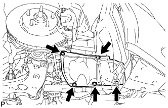
REMOVE FRONT SUSPENSION MEMBER REAR BRACE LH
-
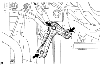
Remove the 3 bolts and front suspension member rear brace LH.
-
-
REMOVE FRONT SUSPENSION MEMBER REAR BRACE RH
Tech Tips
Use the same procedures described for the LH side.
-
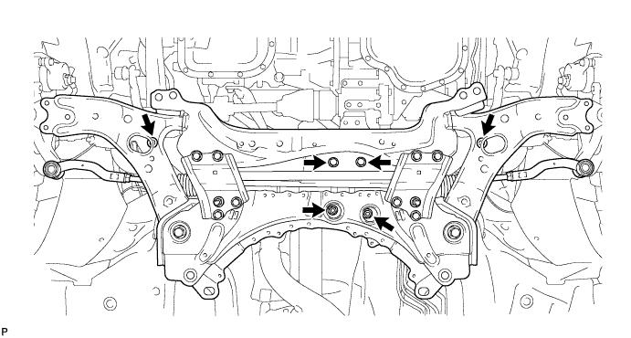
REMOVE FRONT SUSPENSION CROSSMEMBER SUB-ASSEMBLY
-
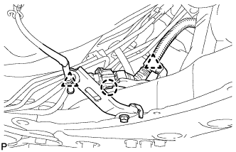
Detach the 2 clamps and claw, and disconnect the oxygen sensor wire from the front suspension crossmember.
-
Support the front suspension crossmember with a transmission jack.
-
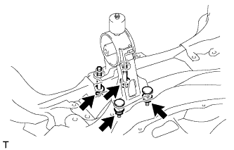
Remove the 4 bolts, 2 nuts and front suspension crossmember.
-
-
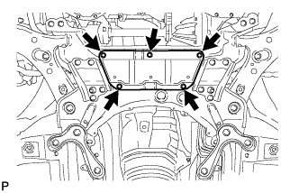
REMOVE REAR ENGINE MOUNTING INSULATOR
Tech Tips
Perform this procedure only when replacement of the engine mounting insulator is necessary.
-
Remove the 2 nuts, 2 bolts and engine mounting insulator.
-
-
REMOVE NO. 1 STEERING COLUMN HOLE COVER SUB-ASSEMBLY
-
Remove the No. 1 steering column hole cover from the steering link.
-
-
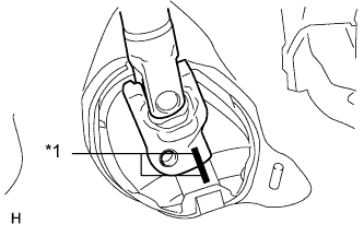
REMOVE STEERING INTERMEDIATE SHAFT
-
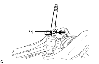
Text in Illustration *1 Matchmark Place matchmarks on the steering intermediate shaft and steering link.
-
Remove the bolt and steering intermediate shaft from the steering link.
-
-
REMOVE STEERING LINK ASSEMBLY
-
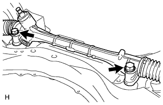
Remove the 2 bolts, 2 nuts and steering link from the front suspension crossmember.
Note
Because the nut has its own stopper, do not turn the nut. Loosen the bolt with the nut fixed in place.
-
-
SECURE STEERING LINK ASSEMBLY
-
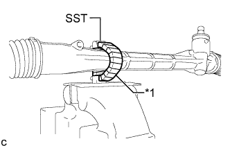
Text in Illustration *1 Protective Tape Using SST, secure the steering link between aluminum plates in a vise.
- SST
- 09612-00012
Tech Tips
Tape SST before use.
-
-
REMOVE TIE ROD END SUB-ASSEMBLY LH
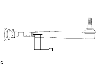
Text in Illustration *1 Matchmark
-
Put matchmarks on the tie rod end LH and steering gear.
-
Remove the tie rod end and lock nut.
-
-
REMOVE TIE ROD END SUB-ASSEMBLY RH
Tech Tips
Use the same procedures described for the LH side.