STEERING LOCK SYSTEM, Diagnostic DTC:B2782

| DTC Code | DTC Name |
|---|---|
| B2782 | Power Source Control ECU Malfunction |
DESCRIPTION
-
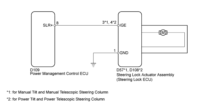
The steering lock ECU activates the steering lock motor by the power from the power management control ECU through the IGE circuit. This prevents the steering from being locked while the vehicle is moving.
-
If NG (PAST) is displayed for Power Supply Open in the Data List, perform troubleshooting according to the procedures below.
The diagnosis information of the steering lock ECU is transmitted to the intelligent tester via the certification ECU as the steering lock actuator assembly (steering lock ECU) is not connected to the CAN communication system.
| DTC Code | Detection Condition | Trouble Area |
|---|---|---|
| B2782 | An IGE power supply circuit malfunction. |
|
WIRING DIAGRAM
INSPECTION PROCEDURE
Tech Tips
When the engine switch is off, the main body ECU may occasionally go into a non-active state called sleep mode. Therefore, before proceeding with the inspection, it is necessary to perform the following steps to wake up the ECU:
With the engine switch off, open the driver door. Then (with the engine switch still off) open and close any door several times at 1.5 second intervals.
Note
-
When disconnecting the cable from the negative (-) battery terminal, some systems need to be initialized after the cable is reconnected Click here.
-
If the steering lock actuator assembly (steering lock ECU) is replaced, with the engine switch off and the shift lever in P (except Manual Transaxle), open and close the driver side door to record the current lock position into the steering lock ECU. If this is not performed, the engine may not start.
-
When replacing the steering lock ECU, registration must be performed. Refer to the Service Bulletin for the registration procedure.
PROCEDURE
-
INSPECT STEERING LOCK ECU
-
for Manual Tilt and Manual Telescopic Steering Column:
-
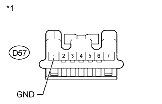
Text in Illustration *1 Front view of wire harness connector
(to Steering Lock ECU)
Disconnect the D57 steering lock ECU connector.
-
Measure the resistance according to the value(s) in the table below.
Standard Resistance Tester Connection Condition Specified Condition D57-1 (GND) - Body ground Always Below 1 Ω -
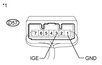
Text in Illustration *1 Component with harness connected
(Steering Lock ECU)
Reconnect the D57 steering lock ECU connector.
-
Turn the engine switch off, make sure that the steering lock is unlocked and move the shift lever to P*.
*: except Manual Transaxle
-
Measure the voltage according to the value(s) in the table below.
Standard Voltage Tester Connection Condition Specified Condition D57-3 (IGE) - D57-1 (GND) Driver side door opened Below 1 V (Steering lock motor operating) D57-3 (IGE) - D57-1 (GND) Driver side door opened 11 to 14 V (Steering lock motor not operating) Tech Tips
When the steering lock is locked and the engine is switch is turned on (IG), the steering lock motor activates to release the steering lock. The motor operates for 2 to 15 seconds.
-
-
for Power Tilt and Power Telescopic Steering Column:
-
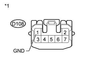
Text in Illustration *1 Front view of wire harness connector
(to Steering Lock ECU)
Disconnect the D108 steering lock ECU connector.
-
Measure the resistance according to the value(s) in the table below.
Standard Resistance Tester Connection Condition Specified Condition D108-1 (GND) - Body ground Always Below 1 Ω -
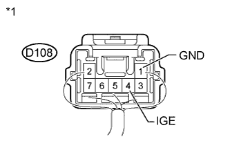
Text in Illustration *1 Component with harness connected
(Steering Lock ECU)
Reconnect the D108 steering lock ECU connector.
-
Turn the engine switch off, make sure that the steering lock is unlocked and move the shift lever to P*.
*: except Manual Transaxle
-
Measure the voltage according to the value(s) in the table below.
Standard Voltage Tester Connection Condition Specified Condition D108-4 (IGE) - D108-1 (GND) Driver side door opened Below 1 V (Steering lock motor operating) D108-4 (IGE) - D108-1 (GND) Driver side door opened 11 to 14 V (Steering lock motor not operating) Tech Tips
When the steering lock is locked and the engine is switch is turned on (IG), the steering lock motor activates to release the steering lock. The motor operates for 2 to 15 seconds.
-
NG 
CHECK HARNESS AND CONNECTOR (STEERING LOCK ECU - POWER MANAGEMENT CONTROL ECU) Click here
OK 
-
-
CLEAR DTC
-
Clear the DTCs Click here.
-
Disconnect and reconnect the cable to the negative (-) battery terminal to clear the malfunction history of Power Supply Open.
NEXT
-
-
READ VALUE USING INTELLIGENT TESTER (POWER SUPPLY OPEN)
-
Check for DTCs Click here.
-
Use the Data List to check if the steering lock control is functioning properly.
Power Source Control Tester Display Measurement Item/Range Normal Condition Diagnostic Note Power Supply Open Open in ECU record/NG (PAST) or OK NG (PAST): Open in ECU
OK: No malfunction
- Result Result Proceed to
-
B2782 is not output
-
"OK" displayed on the tester.
A
-
B2782 is output
-
"NG (PAST)" displayed on the tester.
for Power Tilt and Power Telescopic Steering Column B for Manual Tilt and Manual Telescopic Steering Column C -
B 
REPLACE STEERING LOCK ACTUATOR ASSEMBLY (STEERING LOCK ECU) Click here
C
REPLACE STEERING LOCK ACTUATOR ASSEMBLY (STEERING LOCK ECU) Click here
A 
USE SIMULATION METHOD TO CHECK Click here
-
-
CHECK HARNESS AND CONNECTOR (STEERING LOCK ECU - POWER MANAGEMENT CONTROL ECU)
-
for Manual Tilt and Manual Telescopic Steering Column:
-
Disconnect the D109 power management control ECU connector.
-
Disconnect the D57 steering lock ECU connector.
-
Measure the resistance according to the value(s) in the table below.
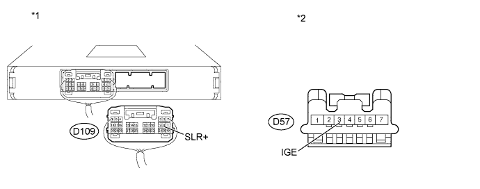
Standard Resistance Tester Connection Condition Specified Condition D57-3 (IGE) - D109-8 (SLR+) Always Below 1 Ω D57-3 (IGE) or D109-8 (SLR+) - Body ground Always 10 kΩ or higher Text in Illustration *1 Rear view of wire harness connector
(to Power Management Control ECU)
*2 Front view of wire harness connector
(to Steering Lock ECU)
-
-
for Power Tilt and Power Telescopic Steering Column:
-
Disconnect the D109 power management control ECU connector.
-
Disconnect the D108 steering lock ECU connector.
-
Measure the resistance according to the value(s) in the table below.
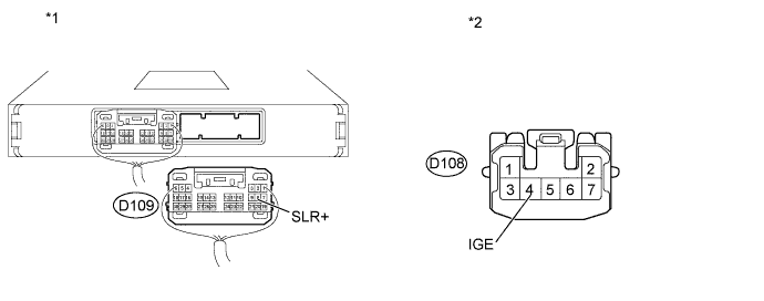
Standard Resistance Tester Connection Condition Specified Condition D108-4 (IGE) - D109-8 (SLR+) Always Below 1 Ω D108-4 (IGE) or D109-8 (SLR+) - Body ground Always 10 kΩ or higher Text in Illustration *1 Rear view of wire harness connector
(to Power Management Control ECU)
*2 Front view of wire harness connector
(to Steering Lock ECU)
-
NG
REPAIR OR REPLACE HARNESS OR CONNECTOR
OK
REPLACE POWER MANAGEMENT CONTROL ECU Click here
-