VACUUM PUMP (for 3ZR-FAE) INSTALLATION

-
INSTALL VACUUM PUMP ASSEMBLY
-
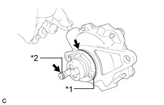
Text in Illustration *1 No. 2 O-ring *2 No. 3 O-ring Apply engine oil to the No. 2 and No. 3 O-rings on the vacuum pump assembly.
Note
When removing and installing the vacuum pump assembly, replace the No. 2 and No. 3 O-rings with new ones.
-
Apply engine oil to the inner surface of the installation hole.
-
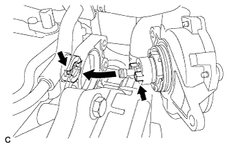
Install the vacuum pump assembly so that the oil pipe engages with the hole of the camshaft and the coupling teeth with the grooves on the camshaft tip.
Note
-
Ensure that the vacuum pump assembly is installed securely.
-
Be careful not to pinch the O-ring.
Tech Tips
Apply engine oil to the O-ring.
-
-
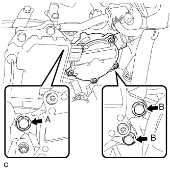
Install the vacuum pump assembly with the 3 bolts.
- Torque:
- 21 N*m { 214 kgf*cm, 15 ft.*lbf }
Note
-
After installation, check that there are no gaps between the matching surfaces and that the vacuum pump assembly is not installed at an angle.
-
As 2 different lengths of bolts are used, make sure to check the proper installation positions before installing them.
-
After tightening the bolts, ensure that the contact surface of the vacuum pump assembly is flush with the cylinder head.
Tech Tips
-
Bolt length
Bolt A: 25 mm
Bolt B: 45 mm
-
-
CONNECT UNION TO CONNECTOR TUBE HOSE
-
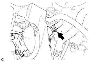
Connect the vacuum hose and move the clip.
-
-
INSPECT VACUUM PUMP OPERATION
-
Remove the No. 2 cylinder head cover.
-
Slide the clip and disconnect the union to connector tube hose from the vacuum pump.
-
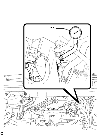
Text in Illustration *1 Vacuum Gauge Connect the hose of a vacuum gauge to the vacuum pump.
-
Start the engine and warm it up for more than 2 minutes.
-
With the engine idling, measure the negative pressure of the vacuum pump.
Standard pressure Higher than 87 kPa (650 mmHg, 25.6 in.Hg) Tech Tips
-
The vacuum pump assembly is listed as one of the 200000 km (124000 mile) maintenance parts. Make sure to disassemble and inspect it every 200000 km (124000 miles) and replace parts as necessary.
-
After disassembling and checking the vacuum pump, check the vacuum pump assembly function.
-
-
Remove the vacuum gauge from the vacuum pump.
-
Connect the union to connector tube hose to the vacuum pump with the clip.
-
Install the No. 2 cylinder head cover.
-
-
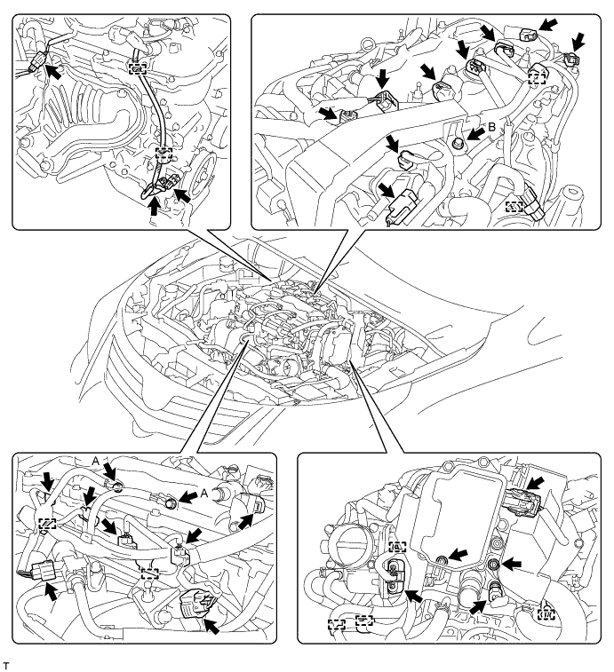
CONNECT ENGINE WIRE
-
Attach the 10 clamps, and then connect the connectors.
-
Connect the engine wire with the 3 bolts and 2 nuts.
- Torque:
- for bolt A
- 8.4 N*m { 86 kgf*cm, 74 in.*lbf }
- for bolt B
- 10 N*m { 102 kgf*cm, 7 ft.*lbf }
- for nut
- 8.4 N*m { 86 kgf*cm, 74 in.*lbf }
-
-
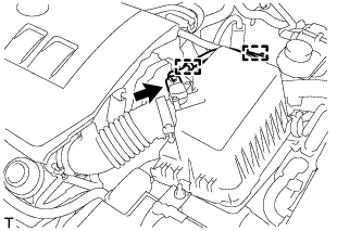
INSTALL AIR CLEANER CASE SUB-ASSEMBLY
-
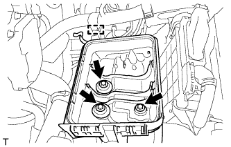
Install the air cleaner case with the 3 bolts.
- Torque:
- 7.0 N*m { 71 kgf*cm, 62 in.*lbf }
-
Attach the wire harness clamp to the air cleaner case.
-
-
INSTALL AIR CLEANER CAP SUB-ASSEMBLY
-
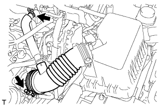
Connect the air cleaner cap with the band.
-
Connect the ventilation hose.
-
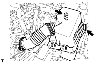
Connect the 2 clamps.
-
Attach the wire harness to the 2 clamps.
-
Connect the mass air flow meter connector.
-
-
INSTALL NO. 2 CYLINDER HEAD COVER
-
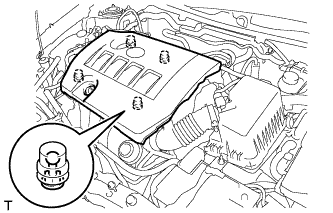
Attach the 4 clips to install the cover.
Note
-
Be sure to attach the clips securely.
-
Do not apply excessive force or hit the cover to attach the clips. This may cause the cover to break.
-
-