VEHICLE STABILITY CONTROL SYSTEM VSC OFF Indicator Light Remains ON
DESCRIPTION
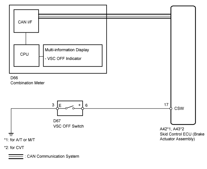
The skid control ECU is connected to the combination meter via CAN communication.
Pressing the VSC OFF switch turns off traction control and pressing and holding this switch turns off traction control and VSC. If VSC turns off, the VSC OFF message will be displayed on the multi-information display and the master warning light will come on.
WIRING DIAGRAM
INSPECTION PROCEDURE
Note
When replacing the skid control ECU (brake actuator assembly), perform engine variant learning Click here.
PROCEDURE
-
CHECK CAN COMMUNICATION SYSTEM
-
Check if a CAN communication system DTC is output Click here.
Result Result Proceed to DTC is not output. A DTC is output. B
B 
GO TO CAN COMMUNICATION SYSTEM (HOW TO PROCEED WITH TROUBLESHOOTING) Click here
A 
-
-
CHECK IF SKID CONTROL ECU CONNECTOR IS SECURELY CONNECTED
-
Check if the skid control ECU connector is securely connected.
OK The connector is securely connected.
NG
CONNECT CONNECTOR TO ECU CORRECTLY
OK
-
-
CHECK HARNESS AND CONNECTOR (CSW TERMINAL)
-
Disconnect the skid control ECU connector.
-
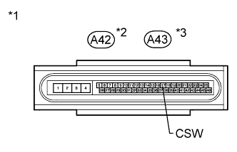
Text in Illustration *1 Front view of wire harness connector
(to Skid Control ECU)
*2 for A/T or M/T *3 for CVT Measure the resistance according to the value(s) in the table below.
Standard Resistance Tester Connection Switch Condition Specified Condition A42 or A43-17 (CSW) - Body ground VSC OFF switch off (Not pressed) 10 kΩ or higher
NG 
INSPECT VSC OFF SWITCH Click here
OK
-
-
INSPECT COMBINATION METER ASSEMBLY
-
Check the combination meter Click here.
Result Result Proceed to The combination meter is normal. A The combination meter is abnormal. B Tech Tips
If troubleshooting has been carried out according to the Problem Symptoms Table, refer back to the table and proceed to the next step before replacing the part Click here.
B
REPLACE COMBINATION METER ASSEMBLY Click here
A 
REPLACE BRAKE ACTUATOR ASSEMBLY Click here
-
-
INSPECT VSC OFF SWITCH
-
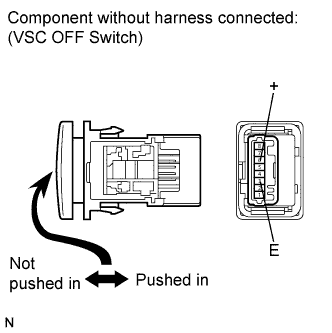
Remove the VSC OFF switch Click here.
-
Measure the resistance according to the value(s) in the table below.
Standard Resistance Tester Connection Switch Condition Specified Condition 6 (+) - 3 (E) Switch is pushed in Below 1 Ω Switch is not pushed in 10 kΩ or higher
NG
REPLACE VSC OFF SWITCH Click here
OK
-
-
CHECK HARNESS AND CONNECTOR (VSC OFF SWITCH - SKID CONTROL ECU/BODY GROUND)
-
Disconnect the skid control ECU connector.
-
Disconnect the VSC OFF switch connector.
-
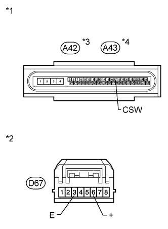
Text in Illustration *1 Front view of wire harness connector
(to Skid Control ECU)
*2 Front view of wire harness connector
(to VSC OFF Switch)
*3 for A/T or M/T *4 for CVT Measure the resistance according to the value(s) in the table below.
Standard Resistance Tester Connection Condition Specified Condition A42 or A43-17 (CSW) - D67-6 (+) Always Below 1 Ω A42 or A43-17 (CSW) - Body ground Always 10 kΩ or higher D67-3 (E) - Body ground Always Below 1 Ω Tech Tips
If troubleshooting has been carried out according to the Problem Symptoms Table, refer back to the table and proceed to the next step before replacing the part Click here.
NG
REPAIR OR REPLACE HARNESS OR CONNECTOR
OK
REPLACE BRAKE ACTUATOR ASSEMBLY Click here
-