VEHICLE STABILITY CONTROL SYSTEM, Diagnostic DTC:C1237/37, C1275/75, C1276/76, C1277/77, C1278/78

| DTC Code | DTC Name |
|---|---|
| C1237/37 | Speed Sensor Rotor Faulty |
| C1275/75 | Abnormal Change in Output Signal of Front Speed Sensor RH (Test Mode DTC) |
| C1276/76 | Abnormal Change in Output Signal of Front Speed Sensor LH (Test Mode DTC) |
| C1277/77 | Abnormal Change in Output Signal of Rear Speed Sensor RH (Test Mode DTC) |
| C1278/78 | Abnormal Change in Output Signal of Rear Speed Sensor LH (Test Mode DTC) |
DESCRIPTION
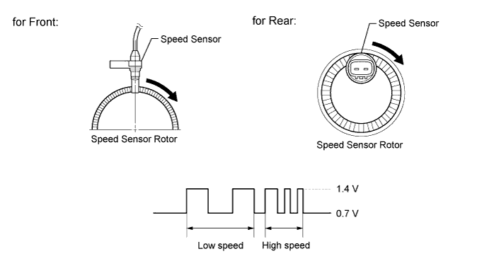
The skid control ECU measures the speed of each wheel by receiving signals from the speed sensors.
These signals are used for recognizing that all 4 wheels are operating properly.
Therefore, all wheel signals must indicate the same speed.
DTCs C1275/75 to C1278/78 are cleared when the speed sensor sends a vehicle speed signal or Test Mode ends. DTCs from C1275/75 to C1278/78 are output only in Test Mode.
| DTC Code | DTC Detection Condition | Trouble Area |
|---|---|---|
| C1237/37 | When any of the following is detected:
|
|
| C1275/75 C1276/76 C1277/77 C1278/78 |
Stored during Test Mode. | Speed sensor rotor (Front axle hub sub-assembly or rear axle hub and bearing assembly) |
Tech Tips
-
DTC C1275/75 is for the front speed sensor RH.
-
DTC C1276/76 is for the front speed sensor LH.
-
DTC C1277/77 is for the rear speed sensor RH.
-
DTC C1278/78 is for the rear speed sensor LH.
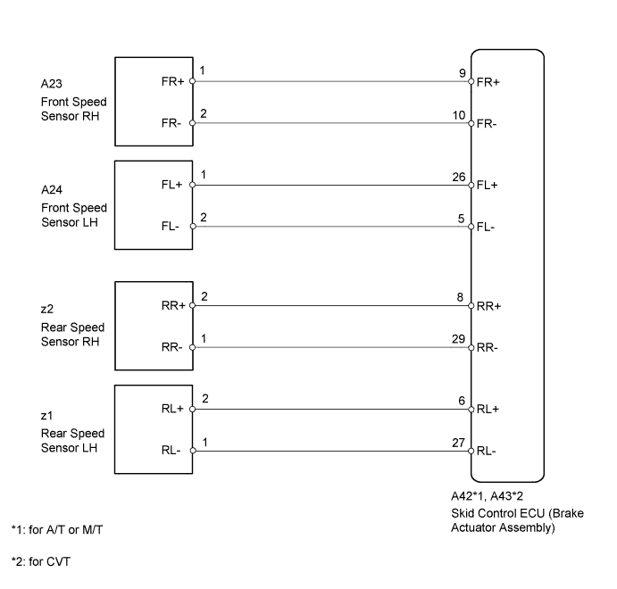
WIRING DIAGRAM
INSPECTION PROCEDURE
Note
When replacing the skid control ECU (brake actuator assembly), perform the engine variant learning Click here.
Tech Tips
When DTC C0200/31, C0205/32, C0210/33, C0215/34, C1330/35, C1331/36, C1332/38 and/or C1333/39 is output together with DTC C1237/37, inspect and repair the trouble areas indicated by DTC C0200/31, C0205/32, C0210/33, C0215/34, C1330/35, C1331/36, C1332/38 and/or C1333/39 first Click here for front speed sensor, and Click here for rear speed sensor).
PROCEDURE
-
CHECK TIRES
-
Check the size and condition of all 4 tires Click here.
Tech Tips
DTC C1237/37 is stored when tire deformation or a difference in tire size is detected.
OK The diameters of all 4 tires are the same. Result Result Proceed to OK for front speed sensor A for rear speed sensor B NG C
B 
C 
REPLACE TIRES SO THAT ALL FOUR TIRES ARE THE SAME SIZE
A 
-
-
CHECK FRONT SPEED SENSOR TIP
-
Remove the front speed sensor Click here.
-
Check the speed sensor tip.
OK No scratches or foreign matter on the sensor tip. Note
Check the speed sensor signal after cleaning or replacement Click here.
NG
CLEAN OR REPLACE FRONT SPEED SENSOR
OK
-
-
CHECK FRONT SPEED SENSOR ROTOR
-
Remove the front speed sensor rotor Click here.
Tech Tips
The front speed sensor rotor is incorporated into the front axle hub sub-assembly.
-
Check the speed sensor rotors.
Result Result Proceed to Scratches, oil or foreign matter on the rotors A No scratches, oil or foreign matter on the rotors B Note
Check the speed sensor signal after cleaning or replacement Click here.
B
CHECK HARNESS AND CONNECTOR (SKID CONTROL ECU - EACH SPEED SENSOR) Click here
A 
CLEAN OR REPLACE FRONT SPEED SENSOR ROTOR
-
-
CHECK HARNESS AND CONNECTOR (SKID CONTROL SENSOR WIRE)
-
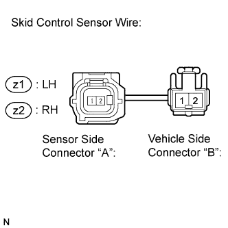
Remove the skid control sensor wire Click here.
-
Measure the resistance according to the value(s) in the table below.
Standard Resistance for RH Tester Connection Condition Specified Condition z2 ("A"-2) - z2 ("B"-1) Always Below 1 Ω z2 ("A"-2) - z2 ("B"-2) Always 10 kΩ or higher z2 ("A"-2) - Body ground Always 10 kΩ or higher z2 ("A"-1) - z2 ("B"-2) Always Below 1 Ω z2 ("A"-1) - z2 ("B"-1) Always 10 kΩ or higher z2 ("A"-1) - Body ground Always 10 kΩ or higher for LH Tester Connection Condition Specified Condition z1 ("A"-2) - z1 ("B"-1) Always Below 1 Ω z1 ("A"-2) - z1 ("B"-2) Always 10 kΩ or higher z1 ("A"-2) - Body ground Always 10 kΩ or higher z1 ("A"-1) - z1 ("B"-2) Always Below 1 Ω z1 ("A"-1) - z1 ("B"-1) Always 10 kΩ or higher z1 ("A"-1) - Body ground Always 10 kΩ or higher Note
Check the speed sensor signal after replacement Click here.
NG
REPLACE SKID CONTROL SENSOR WIRE Click here
OK
-
-
CHECK HARNESS AND CONNECTOR (SKID CONTROL ECU - EACH SPEED SENSOR)
-
Disconnect the skid control ECU connector.
-
Disconnect the front speed sensor connector and/or the rear speed sensor connector.
-
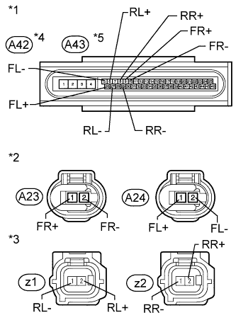
Text in Illustration *1 Front view of wire harness connector
(to Skid Control ECU)
*2 Front view of wire harness connector
(to Front Speed Sensor)
*3 Front view of wire harness connector
(to Rear Speed Sensor)
*4 for A/T or M/T *5 for CVT Measure the resistance according to the value(s) in the table below.
Standard Resistance for Front RH Tester Connection Condition Specified Condition A42 or A43-9 (FR+) - A23-1 (FR+) Always Below 1 Ω A42 or A43-9 (FR+) - Body ground Always 10 kΩ or higher A42 or A43-10 (FR-) - A23-2 (FR-) Always Below 1 Ω A42 or A43-10 (FR-) - Body ground Always 10 kΩ or higher for Front LH Tester Connection Condition Specified Condition A42 or A43-26 (FL+) - A24-1 (FL+) Always Below 1 Ω A42 or A43-26 (FL+) - Body ground Always 10 kΩ or higher A42 or A43-5 (FL-) - A24-2 (FL-) Always Below 1 Ω A42 or A43-5 (FL-) - Body ground Always 10 kΩ or higher for Rear RH Tester Connection Condition Specified Condition A42 or A43-8 (RR+) - z2-2 (RR+) Always Below 1 Ω A42 or A43-8 (RR+) - Body ground Always 10 kΩ or higher A42 or A43-29 (RR-) - z2-1 (RR-) Always Below 1 Ω A42 or A43-29 (RR-) - Body ground Always 10 kΩ or higher for Rear LH Tester Connection Condition Specified Condition A42 or A43-6 (RL+) - z1-2 (RL+) Always Below 1 Ω A42 or A43-6 (RL+) - Body ground Always 10 kΩ or higher A42 or A43-27 (RL-) - z1-1 (RL-) Always Below 1 Ω A42 or A43-27 (RL-) - Body ground Always 10 kΩ or higher
NG
REPAIR OR REPLACE HARNESS OR CONNECTOR
OK
-
-
PERFORM TEST MODE (SIGNAL CHECK)
-
Perform the speed sensor signal check in "Test Mode Procedure" Click here.
OK All Test Mode DTCs are cleared. Result Result Proceed to DTC(s) is not cleared. for front speed sensor A for rear speed sensor B DTCs are cleared. C
B
C
USE SIMULATION METHOD TO CHECK Click here
A
-
-
REPLACE FRONT SPEED SENSOR
-
Turn the ignition switch off.
-
Replace the front speed sensor Click here.
Note
Check the speed sensor signal after replacement Click here.
NEXT
-
-
RECONFIRM DTC
-
Clear the DTCs Click here.
-
Start the engine.
-
Drive the vehicle at a speed of 20 km/h (12 mph) or more for at least 60 seconds.
-
Check if the same DTC is output Click here.
Result Result Proceed to DTC C1237/37 is output. A DTC C1237/37 is not output. B
B
END
A
-
-
REPLACE FRONT SPEED SENSOR ROTOR
-
Turn the ignition switch off.
-
Replace the front axle hub sub-assembly (front speed sensor rotor) Click here.
Tech Tips
The front speed sensor rotor is incorporated into the front axle hub sub-assembly.
If the front speed sensor rotor needs to be replaced, replace it together with the front axle hub sub-assembly.
Note
Check the speed sensor signal after replacement Click here.
NEXT
-
-
RECONFIRM DTC
-
Clear the DTCs Click here.
-
Start the engine.
-
Drive the vehicle at a speed of 20 km/h (12 mph) or more for at least 60 seconds.
-
Check if the same DTC is output Click here.
Result Result Proceed to DTC C1237/37 is output. A DTC C1237/37 is not output. B
B
END
A
REPLACE BRAKE ACTUATOR ASSEMBLY Click here
-
-
REPLACE REAR SPEED SENSOR AND REAR SPEED SENSOR ROTOR
-
Turn the ignition switch off.
-
Replace the rear axle hub and bearing assembly (rear speed sensor and rear speed sensor rotor) Click here.
Tech Tips
The rear speed sensor and rear speed sensor rotor are incorporated into the rear axle hub and bearing assembly.
Note
Check the speed sensor signal after replacement Click here.
NEXT
-
-
RECONFIRM DTC
-
Clear the DTCs Click here.
-
Start the engine.
-
Drive the vehicle at a speed of 20 km/h (12 mph) or more for at least 60 seconds.
-
Check if the same DTC is output Click here.
Result Result Proceed to DTC C1237/37 is output. A DTC C1237/37 is not output. B
B
END
A
REPLACE BRAKE ACTUATOR ASSEMBLY Click here
-