FRONT STABILIZER BAR INSTALLATION

-
INSTALL FRONT NO. 1 STABILIZER BAR BUSHING (for LH Side)
-
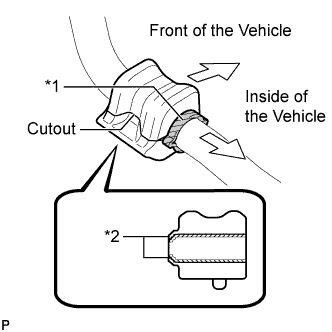
Text in Illustration *1 Stopper *2 Dust Lip Install the front No. 1 stabilizer bar bushing to the front stabilizer bar as shown in the illustration.
Note
-
Install the front No. 1 stabilizer bar bushing so that the dust lips face the outside of the vehicle.
-
Install the front No. 1 stabilizer bar bushing so that the cutout faces the rear of the vehicle.
-
-
-
INSTALL FRONT NO. 1 STABILIZER BAR BUSHING (for RH Side)
Tech Tips
Perform the same procedure as for the LH side.
-
INSTALL FRONT STABILIZER BAR
-
Install the front stabilizer bar to the front suspension crossmember so that the identification mark is positioned on the right side of the vehicle.
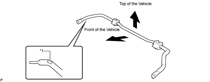
Text in Illustration *1 Identification Mark
-
-
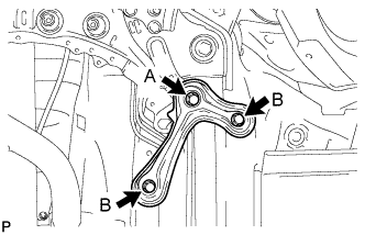
INSTALL FRONT SUSPENSION MEMBER FRONT BRACE LH
-
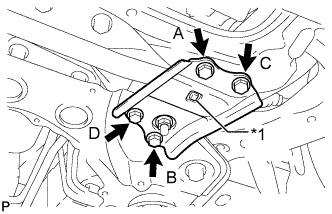
Text in Illustration *1 Protrusion Install the front brace with the 4 bolts.
- Torque:
- 87 N*m { 887 kgf*cm, 64 ft.*lbf }
Note
-
Tighten the bolts in the order of B, C, D and A.
-
Make sure that the protrusion of the No. 1 front stabilizer bar bushing protrudes from the hole of the front suspension member front brace LH when installing the front suspension member front brace LH.
-
-
INSTALL FRONT SUSPENSION MEMBER FRONT BRACE RH
-
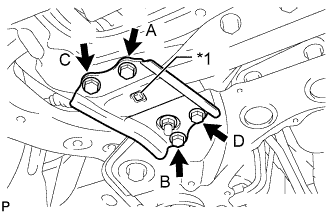
Text in Illustration *1 Protrusion Install the front brace with the 4 bolts.
- Torque:
- 87 N*m { 887 kgf*cm, 64 ft.*lbf }
Note
-
Tighten the bolts in the order of B, C, D and A.
-
Make sure that the protrusion of the No. 1 front stabilizer bar bushing protrudes from the hole of the front suspension member front brace RH when installing the front suspension member front brace RH.
-
-
TEMPORARILY INSTALL FRONT NO. 1 LOWER SUSPENSION ARM SUB-ASSEMBLY LH
-
Position the front suspension crossmember on a level surface.
-
Temporarily install the front lower suspension arm LH to the front suspension crossmember with the 2 bolts and nut.
Note
Because the nut has its own stopper, do not turn the nut. Tighten the bolt with the nut fixed in place.
-
-
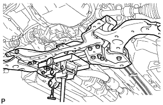
INSTALL FRONT SUSPENSION CROSSMEMBER SUB-ASSEMBLY
-
Support the front suspension crossmember with a transmission jack.
-
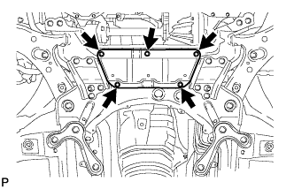
Install the front suspension crossmember and 4 front suspension member mounting stoppers with the 4 bolts and 2 nuts, and tighten the bolts and nuts in several steps while alternately inserting SST into the left and right reference holes of the front suspension crossmember.
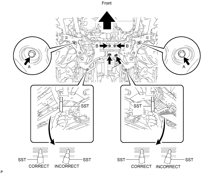
- SST
- 09670-00020
- Torque:
- for bolt A
- 137 N*m { 1397 kgf*cm, 101 ft.*lbf }
- for bolt B and nut B
- 95 N*m { 969 kgf*cm, 70 ft.*lbf }
-
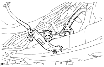
Attach the 2 clamps and claw to connect the oxygen sensor wire to the front suspension crossmember.
-
-
INSTALL FRONT SUSPENSION MEMBER REAR BRACE LH
-
Install the rear brace with the 3 bolts.
- Torque:
- for bolt A
- 137 N*m { 1397 kgf*cm, 101 ft.*lbf }
- for bolt B
- 93 N*m { 948 kgf*cm, 69 ft.*lbf }
-
-
INSTALL FRONT SUSPENSION MEMBER REAR BRACE RH
Tech Tips
Perform the same procedure as for the LH side.
-
INSTALL FRONT SUSPENSION MEMBER REINFORCEMENT LH
-
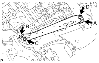
Install the reinforcement with the 4 bolts.
- Torque:
- 96 N*m { 979 kgf*cm, 71 ft.*lbf }
Note
Tighten the bolts in the order of C, B, D and A.
-
-
INSTALL FRONT SUSPENSION MEMBER REINFORCEMENT RH
-
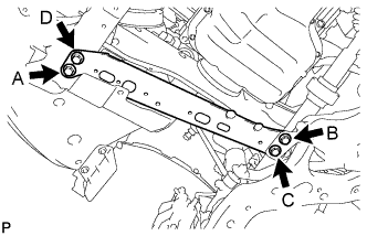
Install the reinforcement with the 4 bolts.
- Torque:
- 96 N*m { 979 kgf*cm, 71 ft.*lbf }
Note
Tighten the bolts in the order of C, B, D and A.
-
-
CONNECT FRONT NO. 1 LOWER SUSPENSION ARM SUB-ASSEMBLY LH
-
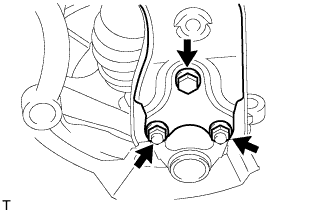
Connect the suspension lower arm to the lower ball joint with the bolt and 2 nuts.
- Torque:
- 89 N*m { 908 kgf*cm, 66 ft.*lbf }
-
-
CONNECT FRONT NO. 1 LOWER SUSPENSION ARM SUB-ASSEMBLY RH
Tech Tips
Perform the same procedure as for the LH side.
-
CONNECT TIE ROD END SUB-ASSEMBLY LH
-
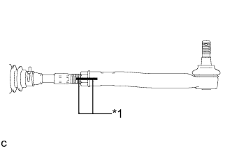
Text in Illustration *1 Matchmark Install the lock nut and tie rod end to the steering gear so that the matchmarks align.
Tech Tips
After adjusting toe-in, tighten the lock nut to the specified torque.
-
-
CONNECT TIE ROD END SUB-ASSEMBLY RH
Tech Tips
Perform the same procedure as for the LH side.
-
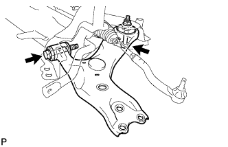
CONNECT FRONT STABILIZER LINK ASSEMBLY LH
-
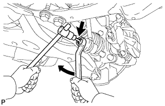
Connect the front stabilizer link to the front stabilizer bar with the nut.
- Torque:
- 74 N*m { 755 kgf*cm, 55 ft.*lbf }
Tech Tips
If the ball joint turns together with the nut, use a 6 mm hexagon wrench to hold the stud bolt.
-
-
CONNECT FRONT STABILIZER LINK ASSEMBLY RH
Tech Tips
Perform the same procedure as for the LH side.
-
INSTALL NO. 1 STEERING COLUMN HOLE COVER SUB-ASSEMBLY
-
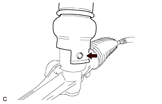
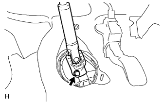
Align the round hole in the No. 1 steering column hole cover with the protrusion of the steering link and install the cover.
-
-
CONNECT NO. 2 STEERING INTERMEDIATE SHAFT ASSEMBLY
-
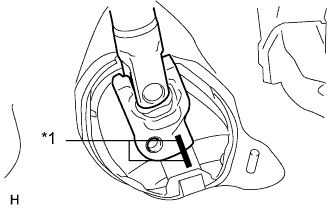
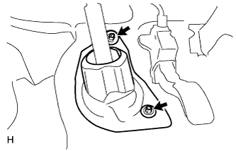
Text in Illustration *1 Matchmark Align the matchmarks on the No. 2 steering intermediate shaft assembly and steering intermediate shaft assembly.
-
Install the bolt.
- Torque:
- 35 N*m { 360 kgf*cm, 26 ft.*lbf }
-
-
INSTALL COLUMN HOLE COVER SILENCER SHEET
-
Install the column hole cover silencer sheet with the 2 clips.
-
Install the floor carpet.
-
-
INSTALL REAR ENGINE UNDER COVER LH
-
Install the under cover with the 5 clips.
-
-
INSTALL REAR ENGINE UNDER COVER RH
Tech Tips
Perform the same procedure as for the LH side.
-
INSTALL FRONT WHEELS
- Torque:
- 103 N*m { 1050 kgf*cm, 76 ft.*lbf }
-
STABILIZE SUSPENSION
-
Lower the vehicle.
-
Bounce the vehicle up and down at the corners several times to stabilize the suspension.
-
-
TIGHTEN FRONT NO. 1 LOWER SUSPENSION ARM SUB-ASSEMBLY LH
-
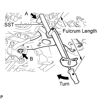
Using SST, tighten bolt A.
- SST
- 09961-01270
- Torque:
- without SST
- 233 N*m { 2376 kgf*cm, 172 ft.*lbf }
- with SST
- 172 N*m { 1755 kgf*cm, 127 ft.*lbf }
Note
-
Because the nut has its own stopper, do not turn the nut. Tighten the bolt with the nut fixed in place.
-
Use a torque wrench with a fulcrum length of 425 mm (1.39 ft.).
-
This torque value is effective when SST is parallel to the torque wrench.
-
The final torque must be applied under standard vehicle height conditions.
-
Tighten bolt B.
- Torque:
- 214 N*m { 2182 kgf*cm, 158 ft.*lbf }
-
-
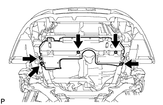
INSTALL NO. 4 CENTER ENGINE UNDER COVER
-
Install the under cover with the 5 clips.
-
-
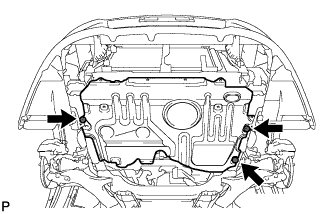
INSTALL NO. 1 ENGINE UNDER COVER
-
Install the under cover with the 5 clips.
-
-
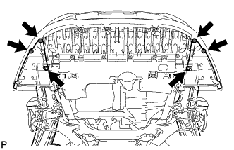
INSTALL NO. 1 ENGINE UNDER COVER (for Rough Road Area Specification Vehicles)
-
Install the under cover with the 3 bolts.
-
-
INSTALL FRONT LOWER BUMPER ABSORBER
-
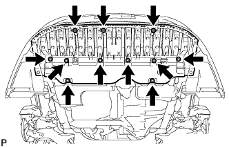
Install the front lower bumper absorber with the 8 bolts and 3 screws.
-
Install the 4 screws and 2 bolts.
-
-
INSPECT AND ADJUST FRONT WHEEL ALIGNMENT
-
Inspect and adjust the front wheel alignment Click here.
-