FRONT LOWER BALL JOINT INSTALLATION

-
INSTALL FRONT LOWER BALL JOINT ASSEMBLY LH
-
Secure the front axle assembly between aluminum plates in a vise.
Note
When using a vise, do not overtighten it.
-
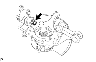
Install the front lower ball joint to the front axle assembly with the nut.
- Torque:
- 133 N*m { 1356 kgf*cm, 98 ft.*lbf }
-
Install a new cotter pin.
Note
If the holes for the cotter pin are not aligned, align the holes by tightening the nut as necessary up to an additional 60°.
-
-
INSTALL FRONT AXLE ASSEMBLY LH
-
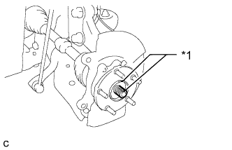
Text in Illustration *1 Matchmark Align the matchmarks and install the front drive shaft assembly to the front axle hub sub-assembly.
-
Install the front axle assembly to the front shock absorber assembly with coil spring with the 2 bolts and 2 nuts.
- Torque:
- 240 N*m { 2447 kgf*cm, 177 ft.*lbf }
Note
Be careful not to damage the drive shaft boot or the magnet rotor of the hub and bearing.
-
-
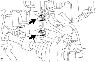
CONNECT FRONT NO. 1 LOWER SUSPENSION ARM SUB-ASSEMBLY LH
-
Connect the suspension lower arm to the lower ball joint with the bolt and 2 nuts.
- Torque:
- 89 N*m { 908 kgf*cm, 66 ft.*lbf }
-
-
CONNECT TIE ROD END SUB-ASSEMBLY LH
-
Connect the tie rod end to the steering knuckle with the nut.
- Torque:
- 49 N*m { 500 kgf*cm, 36 ft.*lbf }
Note
Tighten the nut up to an additional 60° if the holes for the cotter pin are not aligned.
-
Install a new cotter pin.
-
-
INSTALL FRONT DISC
-
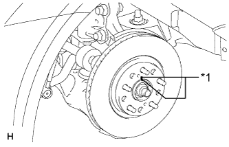
Text in Illustration *1 Matchmark Align the matchmarks of the disc and axle hub, and install the front disc.
Note
When replacing the front disc with a new one, select an installation position where the front disc has minimal runout.
-
-
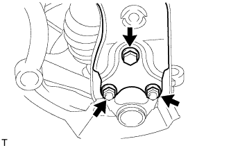
CONNECT FRONT DISC BRAKE CALIPER ASSEMBLY LH
-
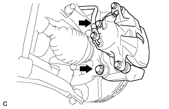
Install the front disc brake cylinder assembly to the steering knuckle with the 2 bolts.
- Torque:
- 107 N*m { 1089 kgf*cm, 79 ft.*lbf }
-
-
CONNECT FRONT FLEXIBLE HOSE
-
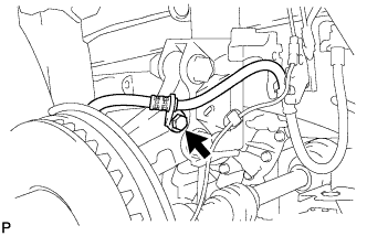
Connect the front flexible hose to the steering knuckle with the bolt.
- Torque:
- 29 N*m { 296 kgf*cm, 21 ft.*lbf }
-
-
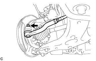
CONNECT FRONT SPEED SENSOR LH
Note
To prevent interference with other parts, do not twist the painted line areas of the sensor wire when installing it.
-
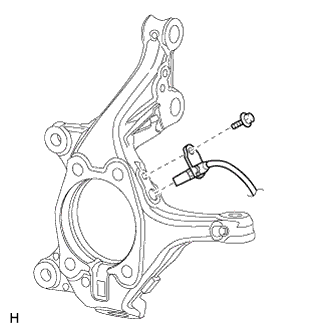
Install the front speed sensor with the bolt.
- Torque:
- 8.5 N*m { 87 kgf*cm, 75 in.*lbf }
Note
-
Keep the sensor tip and sensor installation hole free from foreign matter.
-
Firmly insert the sensor body into the knuckle before tightening the bolt.
-
After installing the sensor to the knuckle, make sure that there is no clearance between the sensor stay and knuckle. Also, make sure that no foreign matter is stuck between the parts.
-
To prevent interference between the sensor and magnetic rotor, do not rotate the sensor body during or after the insertion of the sensor body into the knuckle.
-
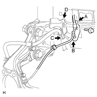
Install the sensor clamp and attach the sensor clip as follows.
-
Simultaneously perform the following: 1) hang the hook part of the sensor clamp (labeled A) on the flexible hose bracket (labeled D) and 2) insert the hook part of the sensor clamp (labeled B) into the flexible hose bracket (labeled C).
Note
Do not twist the sensor wire when installing the clamp.
-
Install the sensor clamp to the flexible hose clamp and flexible hose bracket with the bolt.
- Torque:
- 29 N*m { 296 kgf*cm, 21 ft.*lbf }
-
Attach the sensor clip to the hole in the lower absorber bracket.
-
-
Install the sensor clamp and attach the sensor clip as follows.
-
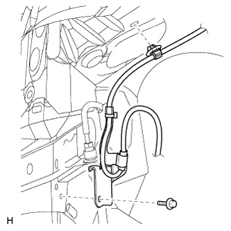
Set the sensor clamp on the side member, and then install the bolt.
- Torque:
- 8.5 N*m { 87 kgf*cm, 75 in.*lbf }
Note
Do not twist the sensor wire when installing the clamp.
-
Attach the sensor clip to the hole in the apron.
-
-
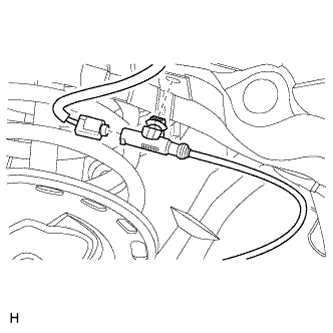
Connect the connector.
-
Attach the connector clip to the hole in the cowl top side.
-
-
INSTALL FRONT AXLE SHAFT NUT LH
-
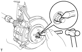
Using a chisel and a hammer, stake the front axle shaft nut.
-
-
INSTALL FRONT WHEEL
- Torque:
- 103 N*m { 1050 kgf*cm, 76 ft.*lbf }
-
INSPECT AND ADJUST FRONT WHEEL ALIGNMENT
-
Inspect and adjust the front wheel alignment Click here.
-
-
CHECK SPEED SENSOR SIGNAL
-
w/o VSC:
Check the speed sensor signal Click here.
-
w/ VSC:
Check the speed sensor signal Click here.
-
-
ADJUST HEADLIGHT ASSEMBLY
-
for Halogen Headlight:
Adjust the headlight assembly Click here.
-
for HID Headlight:
Adjust the headlight assembly Click here.
-