FRONT LOWER BALL JOINT REMOVAL

-
REMOVE FRONT WHEEL
-
REMOVE FRONT AXLE SHAFT NUT LH
-
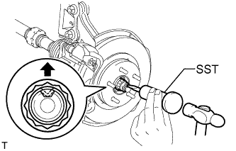
Using SST and a hammer, unstake the staked part of the front axle shaft nut.
- SST
- 09930-00010
Note
Loosen the staked part of the front axle shaft nut completely, otherwise the screw of the drive shaft may be damaged.
-
While applying the brakes, remove the front axle shaft nut.
-
-
DISCONNECT FRONT SPEED SENSOR LH
-
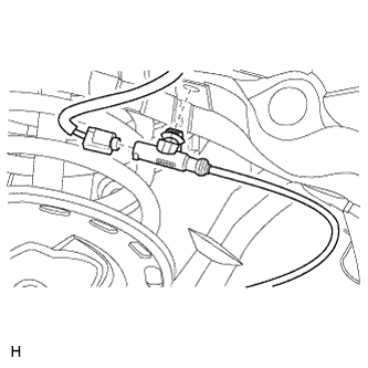
Detach the connector clip.
-
Disconnect the connector.
-
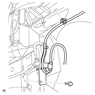
Detach the sensor clip and remove the bolt and sensor clamp.
-
Detach the sensor clip and remove the bolt and sensor clamp.
-
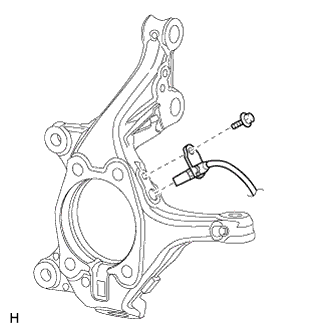
Remove the bolt and front speed sensor from the knuckle.
Note
Keep the sensor tip and sensor installation hole free from foreign matter.
-
-
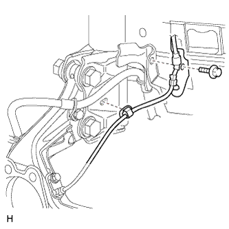
DISCONNECT FRONT FLEXIBLE HOSE
-
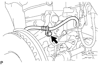
Remove the bolt and disconnect the front flexible hose.
-
-
DISCONNECT TIE ROD END SUB-ASSEMBLY LH
-
Remove the cotter pin and nut.
-
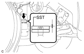
Install SST to the tie rod end.
- SST
- 09960-20010 ( 09961-02060 )
Note
Make sure that the top of SST aligns with the top of the tie rod end.
-
Using SST, separate the tie rod end from the steering knuckle.
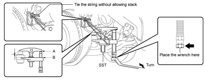
- SST
- 09960-20010 ( 09961-02010 )
Note
Apply grease to the bolt threads and the tip of SST.
Note
-
Be sure to tighten the string firmly to secure SST to the steering knuckle to prevent SST from falling off.
-
Install SST with the center nut so that A and B are parallel. Otherwise, the dust cover may be damaged.
-
Be sure to place the wrench on the part indicated in the illustration.
-
Do not damage the front disc brake dust cover.
-
Do not damage the ball joint dust cover.
-
Do not damage the steering knuckle.
-
-
DISCONNECT FRONT DISC BRAKE CALIPER ASSEMBLY LH
-
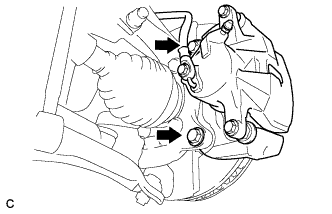
Remove the 2 bolts and front disc brake cylinder assembly from the steering knuckle.
Note
Use wire or an equivalent tool to keep the brake cylinder from hanging down by the flexible hose.
-
-
REMOVE FRONT DISC
-
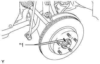
Text in Illustration *1 Matchmark Remove the front disc.
Tech Tips
Put matchmarks on the disc and axle hub.
-
-
DISCONNECT FRONT NO. 1 LOWER SUSPENSION ARM SUB-ASSEMBLY LH
-
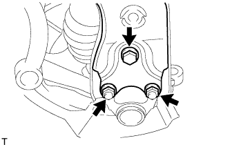
Remove the bolt and 2 nuts.
-
Disconnect the front suspension lower arm from the lower ball joint.
-
-
REMOVE FRONT AXLE ASSEMBLY LH
-
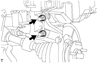
Remove the 2 bolts and 2 nuts, and disconnect the front shock absorber assembly with coil spring from the steering knuckle.
Tech Tips
While holding the nuts in place, loosen and remove the bolts.
-
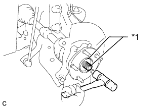
Text in Illustration *1 Matchmark Put matchmarks on the drive shaft and front axle hub sub-assembly.
-
Using a plastic-faced hammer, remove the front axle assembly.
Note
Be careful not to damage the front axle outboard joint boot or the magnet rotor of the hub and bearing. Do not push out the drive shaft from the axle assembly with excessive force.
-
-
REMOVE FRONT LOWER BALL JOINT ASSEMBLY LH
-
Secure the front axle assembly between aluminum plates in a vise.
Note
When using a vise, do not overtighten it.
-
Remove the cotter pin and nut.
-
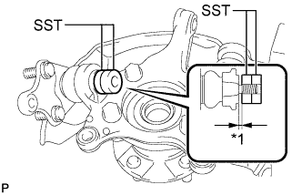
Text in Illustration *1 1 mm Install SST to the front lower ball joint as shown in the illustration.
- SST
- 09960-20010 ( 09961-02050, 09961-02050 )
Note
Make sure that the clearance measurement between SST and the front axle assembly is 1 mm (0.03937 in.).
-
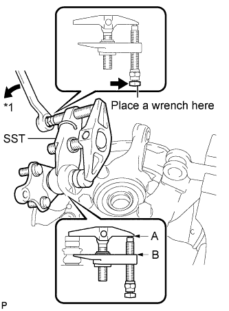
Text in Illustration *1 Turn Using SST, remove the front lower ball joint from the front axle assembly as shown in the illustration.
- SST
- 09960-20010 ( 09961-02010, 09961-02050, 09961-02050 )
Note
-
Install SST so that A and B are parallel.
-
Be sure to turn the part indicated in the illustration with a wrench.
-
Do not damage the front lower ball joint dust cover.
-