FRONT AXLE HUB INSTALLATION

-
INSTALL FRONT AXLE HUB SUB-ASSEMBLY LH
-
Hold the front axle assembly in a vise between aluminum plates.
Note
When using a vise, do not overtighten it.
-
Install the front brake dust cover to the steering knuckle.
-
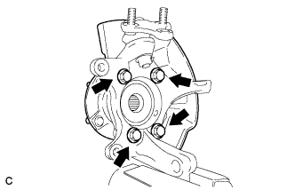
Install the front axle hub sub-assembly with the 4 bolts.
- Torque:
- 96 N*m { 979 kgf*cm, 71 ft.*lbf }
Note
Do not place the magnet rotor side of the hub bearing so that it is facing downward, and do not allow the magnet rotor side to become damaged or contact foreign matter.
-
-
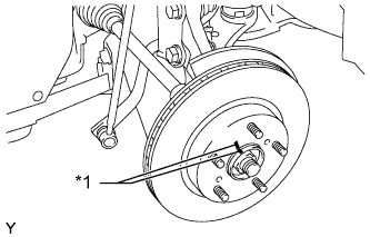
INSTALL FRONT AXLE ASSEMBLY LH
-
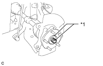
Text in Illustration *1 Matchmark Align the matchmarks and install the front drive shaft assembly to the front axle hub sub-assembly.
-
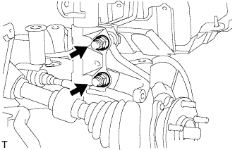
Install the front axle assembly to the front shock absorber assembly with coil spring with the 2 bolts and 2 nuts.
- Torque:
- 240 N*m { 2447 kgf*cm, 177 ft.*lbf }
Note
Be careful not to damage the drive shaft boot or the magnet rotor of the hub and bearing.
-
-
CONNECT FRONT NO. 1 SUSPENSION LOWER ARM SUB-ASSEMBLY LH
-
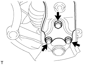
Connect the suspension lower arm to the lower ball joint with the bolt and 2 nuts.
- Torque:
- 89 N*m { 908 kgf*cm, 66 ft.*lbf }
-
-
CONNECT TIE ROD END SUB-ASSEMBLY LH
-
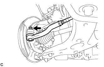
Connect the tie rod end to the steering knuckle with the nut.
- Torque:
- 49 N*m { 500 kgf*cm, 36 ft.*lbf }
Note
Tighten the nut up to an additional 60° if the holes for the cotter pin are not aligned.
-
Install a new cotter pin.
-
-
INSTALL FRONT DISC
-
Text in Illustration *1 Matchmark Align the matchmarks of the disc and axle hub and install the disc.
-
-
INSTALL DISC BRAKE CYLINDER ASSEMBLY LH
-
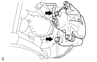
Install the front disc brake cylinder assembly to the steering knuckle with the 2 bolts.
- Torque:
- 107 N*m { 1089 kgf*cm, 79 ft.*lbf }
-
-
INSTALL FRONT AXLE SHAFT NUT LH
-
Clean the threaded parts on the drive shaft and a new axle shaft nut using a non-residue solvent.
Note
-
Be sure to perform this work for a new drive shaft.
-
Keep the threaded parts free of oil and foreign objects.
-
-
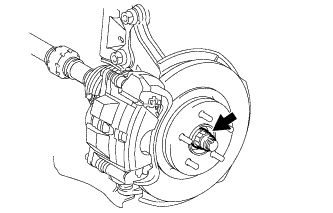
Using a 30 mm socket wrench, temporarily install the axle shaft nut.
- Torque:
- 216 N*m { 2203 kgf*cm, 159 ft.*lbf }
Tech Tips
Stake the nut after inspecting for looseness and runout in the following steps.
-
-
REMOVE DISC BRAKE CYLINDER ASSEMBLY LH
-
REMOVE FRONT DISC
-
INSPECT FRONT AXLE HUB BEARING LOOSENESS
-
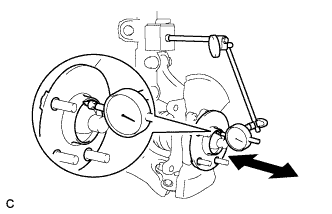
Using a dial indicator, check for looseness near the center of the front axle hub sub-assembly.
Maximum looseness 0.05 mm (0.00197 in.) Note
Make sure that the dial indicator is set perpendicular to the measurement surface.
If the looseness more than the maximum, replace the front axle hub sub-assembly.
-
-
INSPECT FRONT AXLE HUB RUNOUT
-
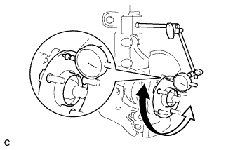
Using a dial indicator, check for runout on the surface of the front axle hub sub-assembly outside the front hub bolts.
Maximum 0.05 mm (0.00197 in.) Note
Make sure that the dial indicator is set perpendicular to the measurement surface.
If the runout more than the maximum, replace the front axle hub sub-assembly.
-
-
INSTALL FRONT DISC
-
Text in Illustration *1 Matchmark Align the matchmarks of the disc and axle hub and install the disc.
Note
When replacing the disc with a new one, select the installation position where the front disc has the smallest runout.
-
-
INSTALL DISC BRAKE CYLINDER ASSEMBLY LH
-
Install the front disc brake cylinder assembly to the steering knuckle with the 2 bolts.
- Torque:
- 107 N*m { 1089 kgf*cm, 79 ft.*lbf }
-
-
INSTALL FRONT FLEXIBLE HOSE
-
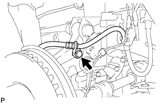
Install the front flexible hose to the steering knuckle with the bolt.
- Torque:
- 29 N*m { 296 kgf*cm, 21 ft.*lbf }
-
-
INSTALL FRONT SPEED SENSOR LH
-
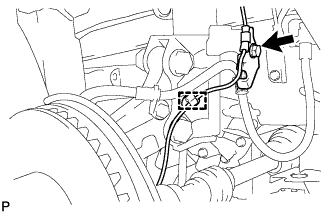
Install the front speed sensor wire and front flexible hose to the front shock absorber with the bolt, and attach the clamp.
- Torque:
- 29 N*m { 296 kgf*cm, 21 ft.*lbf }
Tech Tips
Install the front flexible hose first and then the speed sensor wire bracket.
Note
Do not twist the front speed sensor wire when installing it.
-
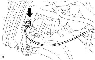
Install the front speed sensor to the steering knuckle with the bolt.
- Torque:
- 8.5 N*m { 87 kgf*cm, 75 in.*lbf }
Note
Do not twist the front speed sensor wire when installing the front speed sensor
-
-
STAKE FRONT AXLE SHAFT NUT LH
-
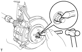
Using a chisel and a hammer, stake the front axle shaft nut.
-
-
INSTALL FRONT WHEEL
- Torque:
- 103 N*m { 1050 kgf*cm, 76 ft.*lbf }
-
INSPECT AND ADJUST FRONT WHEEL ALIGNMENT
-
Inspect and adjust the front wheel alignment Click here.
-
-
CHECK SPEED SENSOR SIGNAL
-
Check the speed sensor signal Click here.
-