REAR LOWER ARM REMOVAL

-
DISCONNECT CABLE FROM NEGATIVE BATTERY TERMINAL
CAUTION:
Wait at least 90 seconds after disconnecting the cable from the negative (-) battery terminal to disable the SRS system.
Note
-
w/ Navigation System for HDD:
After the ignition switch is turned off, the HDD navigation system requires approximately a minute to record various types of memory and settings. As a result, after turning the ignition switch off, wait a minute or more before disconnecting the cable from the negative (-) battery terminal.
-
When disconnecting the cable, some systems need to be initialized after the cable is reconnected Click here.
-
-
REMOVE REAR WHEEL
-
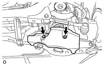
REMOVE REAR SUSPENSION ARM COVER LH
-
Remove the 2 bolts and cover.
-
-
REMOVE REAR NO. 1 SUSPENSION ARM ASSEMBLY LH
-
Turnbuckle Type:
-
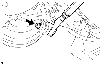
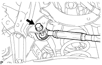
Remove the nut from the axle carrier.
-
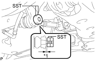
Text in Illustration *1 1 mm Install SST to the rear No. 1 suspension arm as shown in the illustration.
- SST
- 09960-20010 ( 09961-02060 )
Note
Make sure that the clearance measurement between SST and the rear axle assembly is 1 mm (0.0394 in.).
Tech Tips
Use 2 SST of the same type.
-
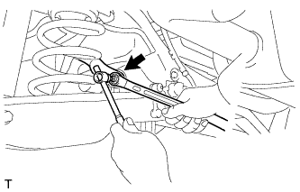
Using SST, disconnect the rear No. 1 suspension arm from the rear axle carrier as shown in the illustration.
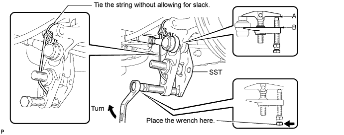
- SST
- 09960-20010 ( 09961-02010 )
Note
-
Apply grease to the bolt threads and tip of SST.
-
Install SST so that A and B are parallel.
-
Be sure to turn the part indicated in the illustration with a wrench.
-
Do not damage the front lower ball joint dust cover.
-
Be sure to tie the string of SST to the vehicle to prevent SST from dropping.
-
Remove the bolt, nut and the rear No. 1 suspension arm.
Note
Since a stopper nut is used, loosen the bolt.
-
-
for Cam Type:
-
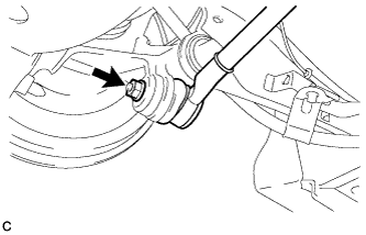
Remove the nut from the axle carrier.
-
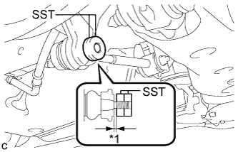
Text in Illustration *1 1 mm Install SST to the rear No. 1 suspension arm as shown in the illustration.
- SST
- 09960-20010 ( 09961-02060 )
Note
Make sure that the clearance measurement between SST and the rear axle assembly is 1 mm (0.0394 in.).
Tech Tips
Use 2 SST of the same type.
-
Using SST, disconnect the rear No. 1 suspension arm from the rear axle carrier as shown in the illustration.
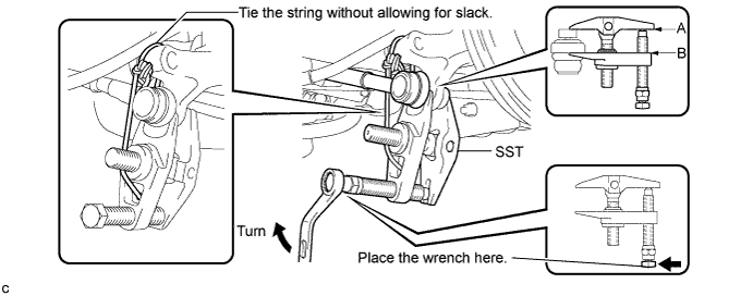
- SST
- 09960-20010 ( 09961-02010 )
Note
-
Apply grease to the bolt threads and tip of SST.
-
Install SST so that A and B are parallel.
-
Be sure to turn the part indicated in the illustration with a wrench.
-
Do not damage the front lower ball joint dust cover.
-
Be sure to tie the string of SST to the vehicle to prevent SST from dropping.
-
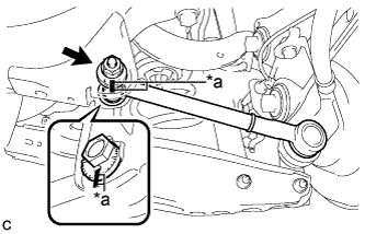
Text in Illustration *a Matchmarks Place matchmarks on the No. 2 camber adjust cam, rear suspension toe adjust cam sub-assembly and rear suspension member sub-assembly.
-
Remove the nut, No. 2 camber adjust cam, rear suspension toe adjust cam sub-assembly and rear No. 1 suspension arm assembly.
Note
Hold the rear suspension toe adjust cam sub-assembly while rotating the nut.
-
-
-
REMOVE REAR HEIGHT CONTROL SENSOR SUB-ASSEMBLY (for HID Headlight)
-
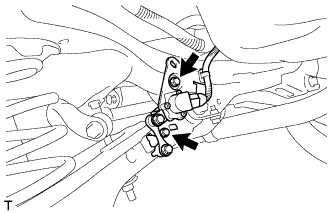
Remove the 2 bolts and rear height control sensor.
-
Disconnect the connector.
-
-
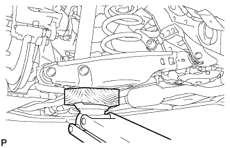
REMOVE REAR STABILIZER LINK ASSEMBLY LH
-
Support the rear No. 2 suspension arm with a jack using a wooden block to avoid damage.
Note
Do not excessively jack up the rear No. 2 suspension arm assembly LH.
Tech Tips
Support the rear shock absorber at a position where it compresses by approximately 20 to 30 mm (0.787 to 1.181 in.).
-
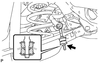
Remove the nut and rear stabilizer cushion.
-
Remove the nut, rear stabilizer link and rear stabilizer cushion.
Tech Tips
If the ball joint turns together with the nut, use a 6 mm hexagon wrench to hold the stud.
-
-
LOOSEN REAR NO. 2 SUSPENSION ARM ASSEMBLY LH
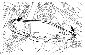
-
Loosen the 2 bolts of the rear No. 2 suspension arm.
Note
-
Do not remove the bolts and nuts. Loosen them.
-
Since a stopper nut is used, loosen the bolt.
-
-
-
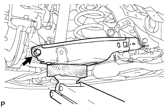
DISCONNECT REAR SHOCK ABSORBER ASSEMBLY LH

-
Support the rear No. 2 suspension arm with a jack using a wooden block.
-
Remove the bolt while holding the nut and disconnect the rear shock absorber.
-
-
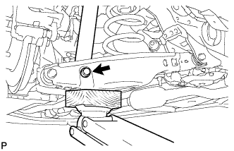
REMOVE REAR COIL SPRING LH
-
Remove the bolt and nut located on the rear axle carrier of the rear No. 2 suspension arm.
-
Lower the jack gradually to remove the rear coil spring with rear upper coil spring insulator.
-
-
REMOVE REAR UPPER COIL SPRING INSULATOR LH
-
Remove the rear upper coil spring insulator from the rear coil spring.
-
-
REMOVE REAR LOWER COIL SPRING INSULATOR LH
-
REMOVE REAR NO. 2 SUSPENSION ARM ASSEMBLY LH
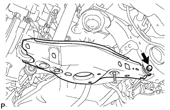
-
Remove the bolt, nut and rear No. 2 suspension arm from the suspension member.
Note
Since a stopper nut is used, loosen the bolt.
-