FRONT DRIVE SHAFT ASSEMBLY (for 1AZ-FE, 3ZR-FE, 3ZR-FAE) REASSEMBLY

-
INSTALL FRONT DRIVE SHAFT HOLE SNAP RING RH
-
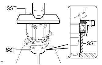
Using SST and a press, press on the drive shaft bearing to the inboard joint RH and bearing case.
- SST
- 09527-10011
- 09710-04081
Note
The bearing should be installed completely.
-
Install the bearing case snap ring to install the bearing case.
-
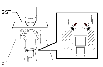
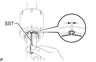
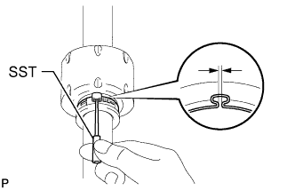
Using a snap ring expander, install a new drive shaft hole snap ring.
-
-
INSTALL FRONT DRIVE SHAFT DUST COVER
-
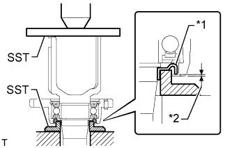
Text in Illustration *1 Dust Cover *2 Depth Using SST and a press, press on a new drive shaft dust cover.
- SST
- 09726-40010
- 09527-10011
Standard depth 1.0 mm (0.0394 in.) Note
Be careful not to damage the dust cover.
-
-
INSTALL FRONT DRIVE SHAFT DUST COVER LH
-
Using SST and a press, press on a new drive shaft dust cover.
- SST
- 09527-10011
Note
-
The dust cover should be installed completely.
-
Be careful not to damage the dust cover.
-
-
INSTALL FRONT DRIVE SHAFT DUST COVER RH
-
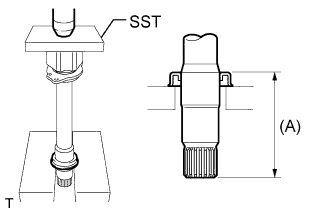
Using SST and a press, press on a new drive shaft dust cover until the dimension from the tip of the center drive shaft to the drive shaft dust cover reaches the specification as shown in the illustration.
- SST
- 09527-10011
Standard dimension (A) 91.0 to 92.0 mm (3.59 to 3.62 in.) Note
-
The dust cover should be installed completely.
-
Be careful not to damage the dust cover.
-
-
INSTALL FRONT AXLE OUTBOARD JOINT BOOT LH
Text in Illustration *1 Vinyl Tape Tech Tips
Before installing the boot, wrap the spline of the drive shaft with vinyl tape to prevent the boot from being damaged.
-
Install new parts to the outboard joint shaft in the following order.
-
No. 2 axle outboard joint boot clamp
-
Outboard joint boot
-
Outboard joint boot clamp
-
-
Pack the outboard joint shaft and boot with grease from the boot kit.
Standard grease capacity 100 to 109 g (3.53 to 3.84 oz.)
-
-
INSTALL FRONT AXLE OUTBOARD JOINT BOOT RH
Tech Tips
Use the same procedures described for the LH side.
-
INSTALL FRONT NO. 2 AXLE OUTBOARD JOINT BOOT CLAMP LH
-
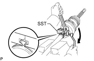
Hold the front drive shaft in a vise between aluminum plates.
-
Secure the No. 2 axle outboard joint boot clamp to the boot.
-
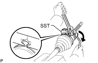
Place SST onto the No. 2 axle outboard joint boot clamp.
- SST
- 09521-24010
-
Tighten SST so that the No. 2 axle outboard joint boot clamp is pinched.
Note
Do not overtighten SST.
-
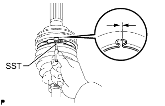
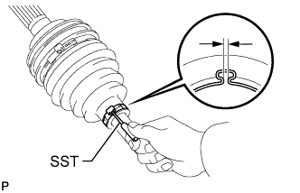
Using SST, adjust the clearance of the clamp.
- SST
- 09240-00020
Standard clearance 0.5 to 1.5 mm (0.0197 to 0.0591 in.) Note
If the measured value exceeds the specified value, retighten the clamp.
-
-
INSTALL FRONT NO. 2 AXLE OUTBOARD JOINT BOOT CLAMP RH
Tech Tips
Use the same procedures described for the LH side.
-
INSTALL FRONT AXLE OUTBOARD JOINT BOOT CLAMP LH
-
Hold the front drive shaft in a vise between aluminum plates.
-
Secure the outboard joint boot clamp to the boot.
-
Place SST onto the outboard joint boot clamp.
- SST
- 09521-24010
-
Tighten SST so that the outboard joint boot clamp is pinched.
Note
Do not overtighten SST.
-
Using SST, adjust the clearance of the clamp.
- SST
- 09240-00020
Standard clearance 0.5 to 1.5 mm (0.0197 to 0.0591 in.) Note
If the measured value exceeds the specified value, retighten the clamp.
-
-
INSTALL FRONT AXLE OUTBOARD JOINT BOOT CLAMP RH
Tech Tips
Use the same procedures described for the LH side.
-
INSTALL FRONT DRIVE SHAFT DAMPER LH
-
Install the drive shaft damper to the drive shaft.
Note
Make sure that the damper is on the shaft groove.
-
Adjust the position of the damper so that the dimension is as described below.
Standard dimension (A) 161 to 165 mm (6.34 to 6.49 in.)
-
-
INSTALL FRONT DRIVE SHAFT DAMPER CLAMP LH
-
Hold the front drive shaft in a vise between aluminum plates.
-
Install a new drive shaft damper clamp to the damper.
Note
Be sure to install the clamp on the inboard joint side in the correct position.
-
Place SST onto the damper clamp.
- SST
- 09521-24010
-
Tighten SST so that the damper clamp is pinched.
Note
Do not overtighten SST.
-
Using SST, adjust the clearance of the damper clamp.
- SST
- 09240-00020
Standard clearance 0.5 to 1.5 mm (0.0197 to 0.0591 in.) Note
If the measured value exceeds the specified value, retighten the clamp.
-
-
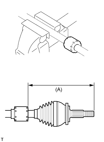
INSTALL FRONT DRIVE SHAFT DAMPER RH
-
Install the drive shaft damper to the drive shaft.
-
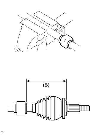
Adjust the position of the damper so that the dimension is as described below.
Standard dimension (B) 161 to 165 mm (6.34 to 6.49 in.)
-
-
INSTALL DRIVE SHAFT DAMPER SETTING CLAMP
-
Hold the front drive shaft in a vise between aluminum plates.
-
Install a new drive shaft damper clamp to the damper.
Note
Be sure to install the clamp on the inboard joint side in the correct position.
-
Place SST onto the damper clamp.
- SST
- 09521-24010
-
Tighten SST so that the damper clamp is pinched.
Note
Do not overtighten SST.
-
Using SST, adjust the clearance of the damper clamp.
- SST
- 09240-00020
Standard clearance 0.5 to 1.5 mm (0.0197 to 0.0591 in.) Note
If the measured value exceeds the specified value, retighten the clamp.
-
-
INSTALL FRONT DRIVE INBOARD JOINT LH
-
Wrap the spline of the outboard joint shaft with vinyl tape to prevent the boot from being damaged.
-
Install new parts to the inboard joint shaft in the following order.
-
Inboard joint boot clamp
-
Inboard joint boot
-
No. 2 axle inboard joint boot clamp
-
-
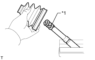
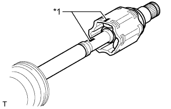
Place the beveled side of the tripod axial spline toward the outboard joint.
-
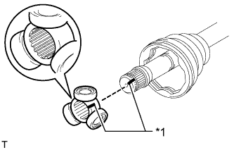
Text in Illustration *1 Matchmark Align the matchmarks placed before removal.
-
Using a brass bar and hammer, tap the tripod onto the drive shaft.
Note
-
Do not tap the rollers.
-
Be sure to install the tripod in the correct direction.
-
-
Pack the inboard joint shaft and boot with grease from the boot kit.
Standard Grease Capacity Item capacity for RH side 155 to 171 g (5.47 to 6.03 oz.) for LH side 163 to 177 g (5.75 to 6.24 oz.) -
Using a snap ring expander, install a new shaft snap ring.
-
Text in Illustration *1 Matchmark Align the matchmarks install the inboard joint to the outboard joint shaft.
-
-
INSTALL FRONT DRIVE INBOARD JOINT RH
Tech Tips
Use the same procedures described for the LH side.
-
INSTALL FRONT AXLE INBOARD JOINT BOOT LH
-
Install the inboard joint boot to the inboard joint.
-

Text in Illustration *1 for LH Side *2 for RH Side Check that the 2 boots are not stretched or contracted when the drive shaft is at the standard length.
Dimension (A) Engine Type Item Dimension 3ZR-FAE and 3ZR-FE for LH side 591.1 mm (23.3 in.) for RH side 888.1 mm (35.0 in.) 1AZ-FE for LH side 581.1 mm (22.9 in.) for RH side 900.1 mm (35.4 in.)
-
-
INSTALL FRONT AXLE INBOARD JOINT BOOT RH
Tech Tips
Use the same procedures described for the LH side.
-
INSTALL FRONT AXLE INBOARD JOINT BOOT CLAMP LH
-
Hold the front drive shaft in a vise between aluminum plates.
-
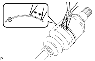
Secure the inboard joint boot clamp to the boot.
-
Place SST onto the inboard joint boot clamp.
- SST
- 09521-24010
-
Tighten SST so that the clamp is pinched.
Note
Do not overtighten SST.
-
Using SST, adjust the clearance of the clamp.
- SST
- 09240-00020
Standard clearance 0.5 to 1.5 mm (0.0197 to 0.0591 in.) Note
If the measured value exceeds the specified value, retighten the clamp.
-
-
INSTALL FRONT AXLE INBOARD JOINT BOOT CLAMP RH
Tech Tips
Use the same procedures described for the LH side.
-
INSTALL FRONT NO. 2 AXLE INBOARD JOINT BOOT CLAMP LH
-
Hold the front drive shaft in a vise between aluminum plates.
-
Secure the inboard joint boot clamp to the boot.
-

Place SST onto the inboard joint boot clamp.
- SST
- 09521-24010
-
Tighten SST so that the clamp is pinched.
Note
Do not overtighten SST.
-
Using SST, adjust the clearance of the clamp.
Standard clearance 0.5 to 1.5 mm (0.0197 to 0.0591 in.) Note
If the measured value exceeds the specified value, retighten the clamp.
-
-
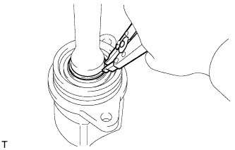
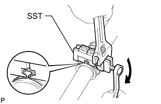
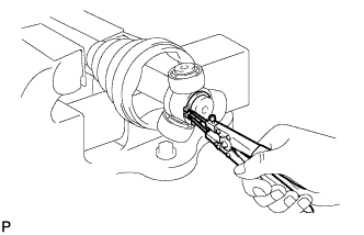
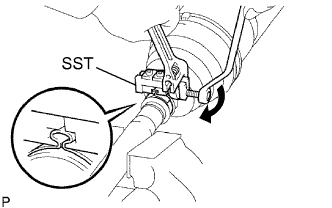
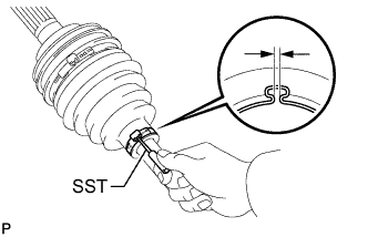
INSTALL FRONT NO. 2 AXLE INBOARD JOINT BOOT CLAMP RH
-
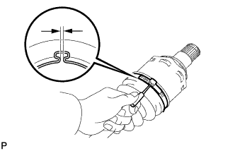
Using needle-nose pliers, install the axle inboard joint boot clamp as shown in the illustration.
Note
Be careful not to damage the boot.
-
-
INSTALL FRONT DRIVE SHAFT HOLE SNAP RING LH
-
Install a new hole snap ring.
-
-
INSPECT DRIVE SHAFT
-
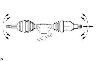
Check that there is no severe play in the radial direction of the outboard joint.
-
Check that the inboard joint slides smoothly in the thrust direction.
-
Check that there is no severe play in the radial direction of the inboard joint.
-
Check the 2 boots for damage.
-
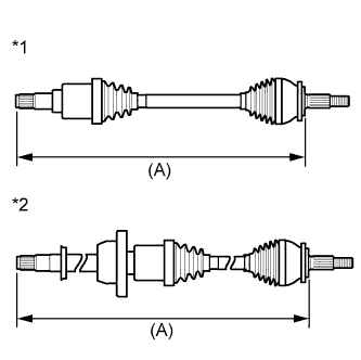
Text in Illustration *1 for LH Side *2 for RH Side Check that the 2 boots are not stretched or contracted when the drive shaft is at the standard length.
Dimension (A) Engine Type Item Dimension 3ZR-FAE and 3ZR-FE for LH side 591.1 mm (23.3 in.) for RH side 888.1 mm (35.0 in.) 1AZ-FE for LH side 581.1 mm (22.9 in.) for RH side 900.1 mm (35.4 in.) If the boots are stretched or contracted, correct them.
-