TRANSMISSION CONTROL CABLE INSTALLATION
-
INSTALL TRANSMISSION CONTROL CABLE ASSEMBLY
Note
Before installing the transmission control cable assembly, check that the park/neutral position switch and shift lever are in neutral.
-
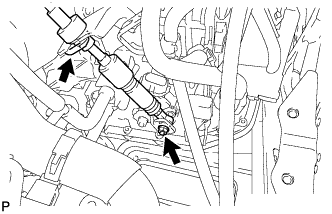
Put the transmission control cable into the cabin and connect the transmission control cable with the 2 nuts.
- Torque:
- 5.0 N*m { 51 kgf*cm, 44 in.*lbf }
-
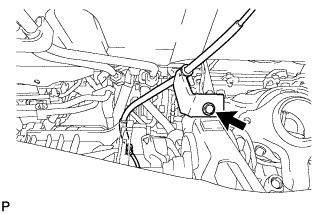
Connect the transmission control cable support with the bolt.
- Torque:
- 5.0 N*m { 51 kgf*cm, 44 in.*lbf }
-
Connect the transmission control cable to the control cable support.
-
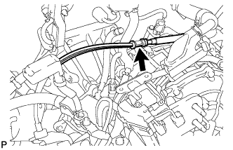
Connect the transmission control cable to the bracket with a new clip.
-
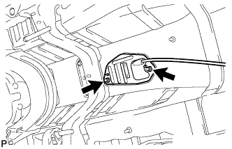
Connect the transmission control cable to the control shaft lever with the nut.
- Torque:
- 12 N*m { 122 kgf*cm, 9 ft.*lbf }
-
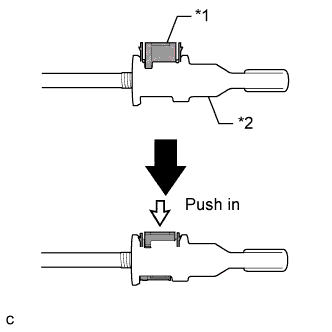
Turn the nut of the transmission control cable 180° counterclockwise. While holding the nut in place, push in the stopper until the stopper clicks twice.
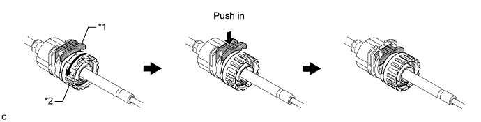
Text in Illustration *1 Stopper *2 Nut -
Install the outer part of the transmission control cable to the shift lever retainer. Check that the spring is positioned at "A" and push in the stopper.
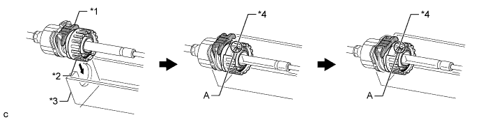
Text in Illustration *1 Stopper *3 Shift Lever Retainer *2 Nut *4 Spring Tech Tips
If the stopper cannot be pushed in, slightly turn the nut clockwise and then push in the stopper again.
-
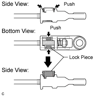
Push the 2 claws together at the top of the transmission control cable lock piece. While holding the 2 claws together, push the 2 lugs on the bottom of the lock piece toward each other and upward to pull out the lock piece.
-
Text in Illustration *1 Lock Piece Connect the end of the cable to the shift lever assembly.
Note
-
Make sure that the lock piece is pulled up.
-
Push on the end of the cable all the way to the base of the pin.
-
-
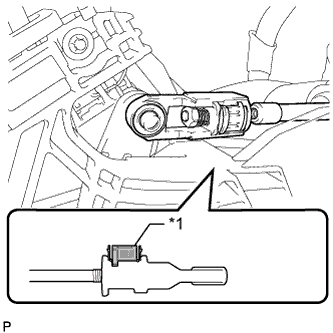
Text in Illustration *1 Lock Piece *2 Adjuster Case Push the lock piece into the adjuster case.
Note
Securely push in the lock piece until it locks.
-
-
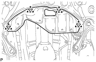
INSTALL FRONT FLOOR NO. 1 HEAT INSULATOR
-
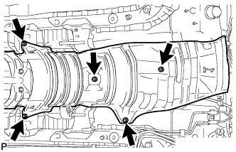
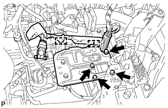
Install the heat insulator with the 5 nuts.
- Torque:
- 5.5 N*m { 56 kgf*cm, 49 in.*lbf }
-
-
INSTALL FRONT EXHAUST PIPE ASSEMBLY
-
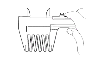
Using a vernier caliper, measure the free length of the compression springs.
Minimum Free Length Item Specified Condition Front side compression spring 41.5 mm (1.63 in.) Rear side compression spring 38.5 mm (1.52 in.) If the free length is less than the minimum, replace the compression spring.
-
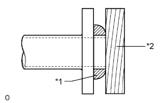
Text in Illustration *1 Gasket *2 Wooden Block Using a plastic-faced hammer and wooden block, tap in a new gasket until its surface is flush with the exhaust manifold.
Note
-
Be sure to install the gasket so that it faces the correct direction.
-
Do not reuse the gasket.
-
Do not damage the gasket.
-
When connecting the exhaust pipe, do not push in the gasket with the exhaust pipe.
-
-
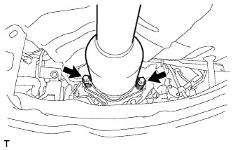
Install the 2 exhaust pipe supports, and then install the front exhaust pipe assembly with the 2 compression springs and 2 bolts.
- Torque:
- 43 N*m { 438 kgf*cm, 32 ft.*lbf }
-
Text in Illustration *1 Gasket *2 Wooden Block Using a plastic-faced hammer and wooden block, tap in a new gasket until its surface is flush with the front exhaust pipe assembly.
Note
-
Be sure to install the gasket so that it faces the correct direction.
-
Do not reuse the gasket.
-
Do not damage the gasket.
-
When connecting the exhaust pipe, do not push in the gasket with the exhaust pipe.
-
-
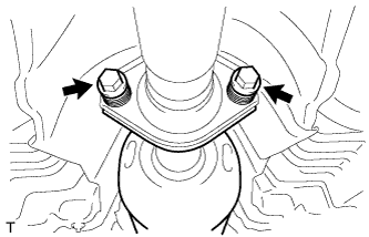
Connect the front exhaust pipe assembly to the tailpipe assembly with the 2 compression springs and 2 bolts.
- Torque:
- 43 N*m { 438 kgf*cm, 32 ft.*lbf }
-
Connect the heated oxygen sensor connector.
-
Attach the clamp to connect the heated oxygen sensor wire harness.
-
-
CONNECT HEATED OXYGEN SENSOR CONNECTOR
-
INSTALL NO. 2 ENGINE UNDER COVER
-
Install the under cover with the 4 clips.
-
-
INSTALL AIR CLEANER CASE SUB-ASSEMBLY
-
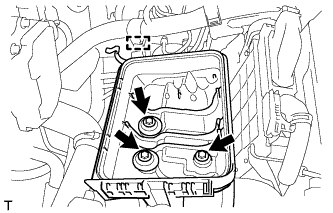
Install the air cleaner case with the 3 bolts.
- Torque:
- 7.0 N*m { 71 kgf*cm, 62 in.*lbf }
-
Attach the wire harness clamp to the air cleaner case.
-
-
INSTALL AIR CLEANER CAP AND HOSE
-
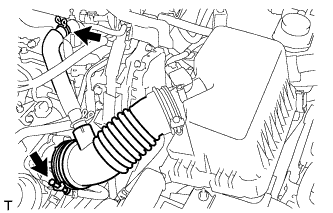
Connect the air cleaner cap with the band.
-
Connect the ventilation hose.
-
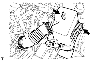
Connect the 2 clamps.
-
Attach the wire harness to the 2 clamps.
-
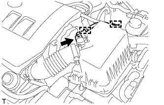
Connect the mass air flow meter connector.
-
-
INSTALL BATTERY CARRIER
-
Install the battery carrier with the 4 bolts.
- Torque:
- 19 N*m { 194 kgf*cm, 14 ft.*lbf }
-
Attach the 2 wire harness clamps.
-
-
INSTALL BATTERY
-
Install the battery tray.
-
Install the battery.
-
Install the battery clamp with the bolt and tighten the nut.
- Torque:
- for bolt
- 17 N*m { 168 kgf*cm, 12 ft.*lbf }
- for nut
- 3.5 N*m { 36 kgf*cm, 31 in.*lbf }
-
Connect the cable to the positive (+) battery terminal.
- Torque:
- 5.4 N*m { 55 kgf*cm, 48 in.*lbf }
-
-
INSTALL NO. 2 CYLINDER HEAD COVER
-
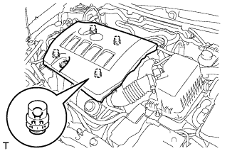
Attach the 4 clips to install the cover.
Note
-
Be sure to attach the clips securely.
-
Do not apply excessive force or hit the cover to attach the clips. This may cause the cover to break.
-
-
-
CONNECT CABLE TO NEGATIVE BATTERY TERMINAL
Note
When disconnecting the cable, some systems need to be initialized after the cable is reconnected Click here.
-
INSTALL RADIATOR SUPPORT OPENING COVER
-
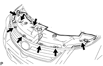
Install the radiator support opening cover with the 8 clips.
-
-
INSTALL ENGINE ROOM SIDE COVER
-

Install the engine room side cover with the clip.
-
-
INSPECT SHIFT LEVER POSITION
-
When moving the shift lever from P to R with the ignition switch ON and the brake pedal depressed, make sure that the shift lever moves smoothly and correctly into position.
-
Start the engine and make sure that the vehicle moves forward after moving the shift lever from N to D and moves in reverse after moving the shift lever to R. If the operation cannot be performed as specified, inspect the park/neutral position switch assembly and check the shift lever assembly installation condition.
-
-
ADJUST SHIFT LEVER POSITION
-
Remove the console box assembly Click here.
-
Apply the parking brake and move the shift lever to N.
-
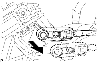
Disconnect the end of the transmission control cable from the shift lever.
-
Text in Illustration *1 Stopper *2 Nut Pull out the stopper of the transmission control cable.
Note
Do not remove the stopper. If the stopper is removed, reinstall it to its original position.
-
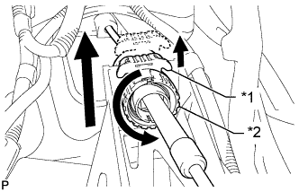
Rotate the nut counterclockwise approximately 180° and, while holding the nut in that position, disconnect the transmission control cable from the shift lever retainer.
Note
Do not over-rotate the nut as it will come off the internal spring and the transmission control cable will not be reusable.
-
Push the 2 claws together at the top of the transmission control cable lock piece. While holding the 2 claws together, push the 2 lugs on the bottom of the lock piece toward each other and upward to pull out the lock piece.
-
Turn the nut of the transmission control cable 180° counterclockwise. While holding the nut in place, push in the stopper until the stopper clicks twice.
Text in Illustration *1 Stopper *2 Nut -
Install the outer part of the transmission control cable to the shift lever retainer. Check that the spring is positioned at "A" and push in the stopper.
Text in Illustration *1 Stopper *3 Shift Lever Retainer *2 Nut *4 Spring Tech Tips
If the stopper cannot be pushed in, slightly turn the nut clockwise and then push in the stopper again.
-
Connect the end of the cable to the shift lever assembly.
Note
-
Check that the lock piece is pulled up.
-
Push on the end of the cable all the way to the base of the pin.
-
-
Text in Illustration *1 Lock Piece *2 Adjuster Case Push the lock piece into the adjuster case.
Note
Securely push in the lock piece until it locks.
-
After adjusting the shift lever position, check the operation and function of the shift lever. If there is a problem, adjust the position again.
-
Install the console box Click here.
-
-
INSTALL CONSOLE BOX ASSEMBLY
-
Install the console box assembly Click here
-