INPUT SHAFT REASSEMBLY

-
INSTALL FRONT INPUT SHAFT BEARING
-
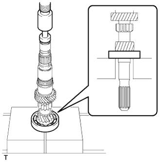
Using SST and a press, press the front input shaft bearing onto the input shaft.
-
-
INSTALL 3RD GEAR NEEDLE ROLLER BEARING
-
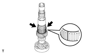
Coat the 2 pieces of the 3rd gear needle roller bearing with gear oil and install them to the input shaft.
-
-
INSTALL 3RD GEAR
-
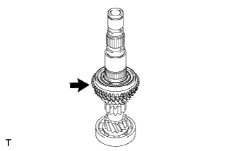
Coat the 3rd gear with gear oil and install it to the input shaft.
-
-
INSTALL NO. 3 SYNCHRONIZER RING
-
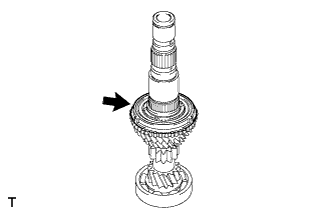
Coat the No. 3 synchronizer ring with gear oil and install it to the 3rd gear.
-
-
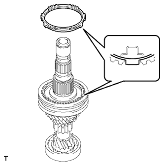
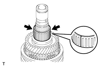
INSTALL NO. 2 TRANSMISSION CLUTCH HUB
-
Coat the No. 2 transmission clutch hub with gear oil.
-
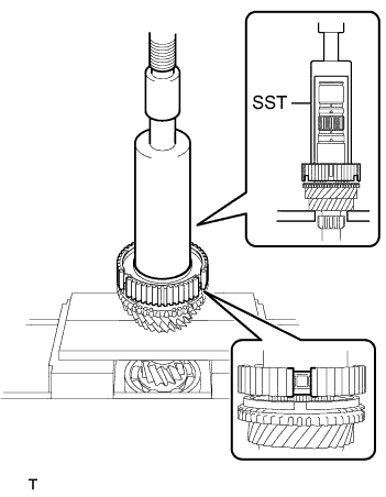
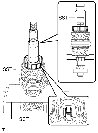
Using SST and a press, press the No. 2 transmission clutch hub onto the input shaft.
- SST
- 09527-21011
- 09316-60011 ( 09316-00011 )
Note
When installing the No. 2 transmission clutch hub, align the protrusion of the No. 3 synchronizer ring with the cutout of the No. 2 transmission clutch hub.
-
-
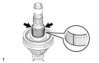
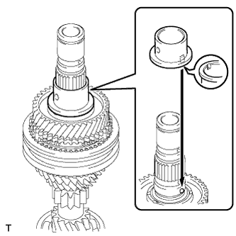
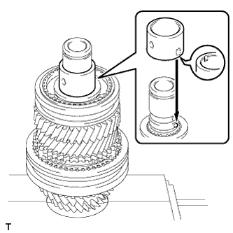
INSTALL NO. 2 CLUTCH HUB SETTING SHAFT SNAP RING
-
Select a new snap ring that will allow minimal axial play.
Standard clearance 0.1 mm (0.00394 in.) or less Standard Snap Ring Thickness Mark Specified Condition Mark Specified Condition 0 2.30 mm (0.0905 in.) 3 2.48 mm (0.0976 in.) 1 2.36 mm (0.0929 in.) 4 2.54 mm (0.0999 in.) 2 2.42 mm (0.0952 in.) 5 2.60 mm (0.1023 in.) -
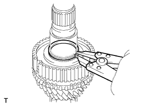
Using a snap ring expander, install the No. 2 clutch hub setting shaft snap ring.
Note
-
Be sure to properly install the snap ring as it easily expands.
-
Do not damage the journal surface of the snap ring.
-
-
-
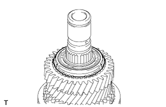
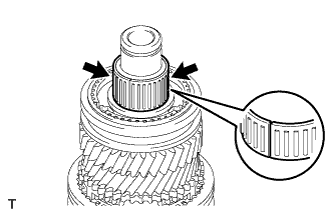
INSTALL NO. 2 SYNCHROMESH SHIFTING KEY
-
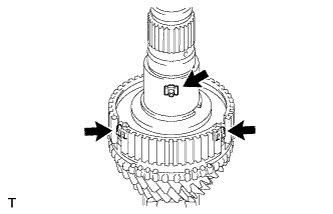
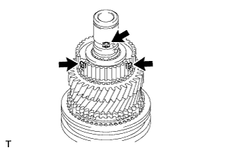
Install the 3 No. 2 synchromesh shifting keys to the No. 2 transmission clutch hub.
-
-
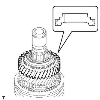
INSTALL NO. 2 TRANSMISSION HUB SLEEVE
-
Coat the No. 2 transmission hub sleeve with gear oil.
-
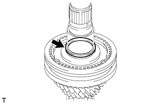
Install the No. 2 transmission hub sleeve to the No. 2 transmission clutch hub.
-
-
INSTALL 4TH GEAR BEARING SPACER
-
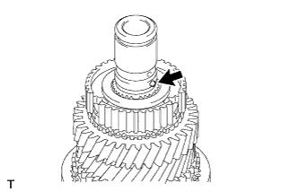
Install the 4th gear bearing spacer to the input shaft.
-
-
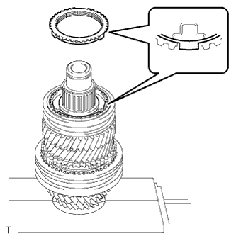
INSTALL 4TH GEAR SYNCHRONIZER RING
-
Coat the 4th gear synchronizer ring with gear oil and install it to the No. 2 transmission clutch hub.
Note
When installing the 4th gear synchronizer ring, align the protrusion of the 4th gear synchronizer ring with the cutout of the No. 2 transmission clutch hub.
-
-
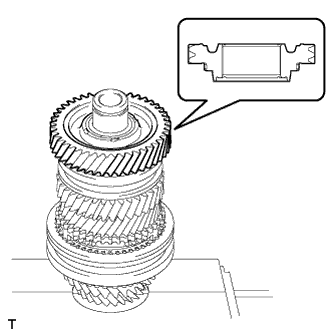
INSTALL 4TH GEAR
-
Coat the 2 pieces of the 4th gear needle roller bearing and 4th gear bearing spacer with gear oil and install the 4th gear needle roller bearing to the input shaft.
Tech Tips
The 4th gear and 4th gear needle roller bearing are supplied as a set. When replacing the 4th gear or 4th gear needle roller bearing, replace them together as a set.
-
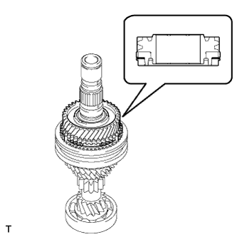
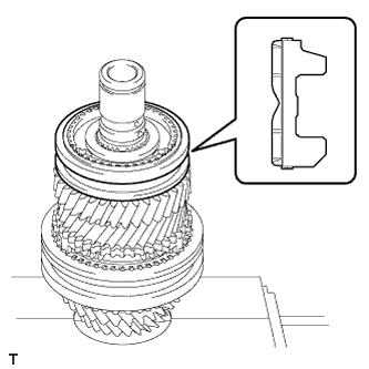
Coat the 4th gear with gear oil and install it to the input shaft.
Note
Install the 4th gear as shown in the illustration.
-
-
INSTALL INNER 5TH GEAR BEARING RACE LOCK BALL
-
Coat the inner 5th gear bearing race lock ball with gear oil and install it to the input shaft.
-
-
INSTALL INNER 5TH GEAR BEARING RACE
-
Coat the inner 5th gear bearing race with gear oil and install it to the input shaft.
Note
Align the groove of the inner 5th gear bearing race with the ball.
-
-
INSTALL 5TH GEAR NEEDLE ROLLER BEARING
-
Coat the 2 pieces of the 5th gear needle roller bearing and inner 5th gear bearing race with gear oil and install the 5th gear needle roller bearing to the input shaft.
-
-
INSTALL 5TH GEAR
-
Coat the 5th gear with gear oil and install it to the input shaft.
Note
Install the 5th gear as shown in the illustration.
-
-
INSTALL NO. 5 SYNCHRONIZER RING
-
Coat the No. 5 synchronizer ring with gear oil and install it to the 5th gear.
-
-
INSTALL NO. 3 TRANSMISSION CLUTCH HUB
-
Coat the No. 3 transmission clutch hub with gear oil.
-
Using SST and a press, press the No. 3 transmission clutch hub onto the input shaft.
- SST
- 09309-37010
- 09527-21011
Note
When installing the No. 3 transmission clutch hub, align the protrusion of the No. 5 synchronizer ring with the cutout of the No. 3 transmission clutch hub.
-
-
INSTALL NO. 3 SYNCHROMESH SHIFTING KEY
-
Install the 3 No. 3 synchromesh shifting keys to the No. 3 transmission clutch hub.
-
-
INSTALL INNER 6TH GEAR BEARING RACE LOCK BALL
-
Coat the inner 6th gear bearing race lock ball with gear oil and install it to the input shaft.
-
-
INSTALL NO. 3 TRANSMISSION HUB SLEEVE
-
Coat the No. 3 transmission hub sleeve with gear oil.
-
Install the No. 3 transmission hub sleeve to the No. 3 transmission clutch hub.
Note
Install the No. 3 transmission hub sleeve as shown in the illustration.
-
-
INSTALL INNER 6TH GEAR BEARING RACE
-
Coat the inner 6th gear bearing race with gear oil and install it to the input shaft.
Note
Align the groove of the inner 6th gear bearing race with the ball.
-
-
INSTALL 6TH GEAR NEEDLE ROLLER BEARING
-
Coat the 2 pieces of the 6th gear needle roller bearing and inner 6th gear bearing race with gear oil and install the 6th gear needle roller bearing to the input shaft.
-
-
INSTALL NO. 5 SYNCHRONIZER RING
-
Coat the No. 5 synchronizer ring with gear oil and install it to the No. 3 transmission clutch hub.
Note
When installing the No. 5 synchronizer ring, align the protrusion of the No. 5 synchronizer ring with the cutout of the No. 3 transmission clutch hub.
-
-
INSTALL 6TH GEAR SUB-ASSEMBLY
-
Coat the 6th gear sub-assembly with gear oil and install it to the input shaft.
Note
Install the 6th gear sub-assembly as shown in the illustration.
-
-
INSTALL REAR INPUT SHAFT RADIAL BALL BEARING
-
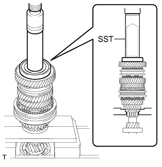
Using SST and a press, press the rear input shaft radial ball bearing onto the input shaft.
- SST
- 09527-21011
- 09608-04031
-
-
INSTALL REAR INPUT SHAFT BEARING SHAFT SNAP RING
-
Select a new snap ring that will allow minimal axial play.
Standard clearance 0.1 mm (0.00394 in.) or less Standard Snap Ring Thickness Mark Specified Condition Mark Specified Condition 0 1.90 mm (0.0748 in.) 6 2.26 mm (0.0889 in.) 1 1.96 m (0.0771 in.) 7 2.32 mm (0.0913 in.) 2 2.02 mm (0.0795 in.) 8 2.38 mm (0.0937 in.) 3 2.08 mm (0.0818 in.) 9 2.44 mm (0.0960 in.) 4 2.14 mm (0.0842 in.) A 2.50 mm (0.0984 in.) 5 2.20 mm (0.0866 in.) - - -
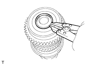
Using a snap ring expander, install the rear input shaft bearing shaft snap ring.
Note
-
Be sure to properly install the snap ring as it easily expands.
-
Do not damage the journal surface of the snap ring.
-
-
-
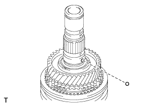
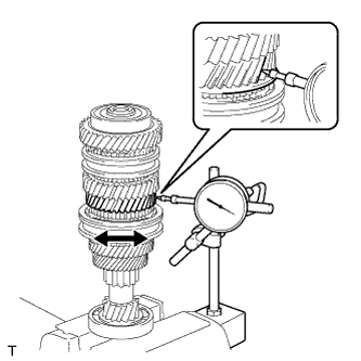
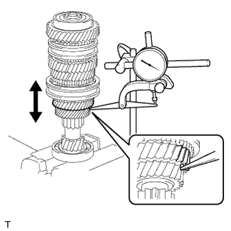
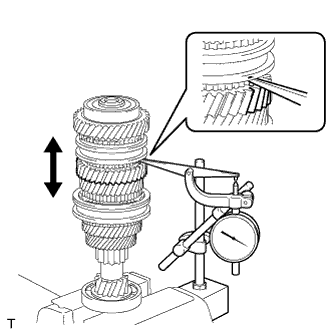
INSPECT 3RD GEAR RADIAL CLEARANCE
-
Using a dial indicator, measure the 3rd gear radial clearance.
Standard clearance 0.009 to 0.047 mm (0.00035 to 0.00185 in.) Maximum clearance 0.047 mm (0.00185 in.) If the clearance is more than the maximum, replace the 3rd gear, 3rd gear needle roller bearing or input shaft. Replace the part or parts determined to be the most likely cause of the problem.
-
-
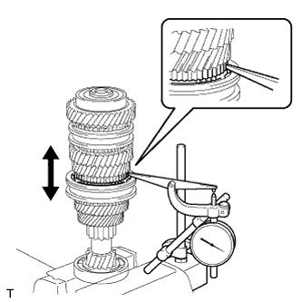
INSPECT 4TH GEAR RADIAL CLEARANCE
-
Using a dial indicator, measure the 4th gear radial clearance between the gear and shaft.
Standard clearance 0.009 to 0.036 mm (0.00035 to 0.00142 in.) Maximum clearance 0.036 mm (0.00142 in.) If the clearance is more than the maximum, replace the 4th gear, 4th gear needle roller bearing or input shaft. Replace the part or parts determined to be the most likely cause of the problem.
-
-
INSPECT 5TH GEAR RADIAL CLEARANCE
-
Using a dial indicator, measure the 5th gear radial clearance between the gear and shaft.
Standard clearance 0.009 to 0.045 mm (0.00035 to 0.00177 in.) Maximum clearance 0.045 mm (0.00177 in.) If the clearance is more than the maximum, replace the 5th gear, 5th gear needle roller bearing, inner 5th gear bearing race or input shaft. Replace the part or parts determined to be the most likely cause of the problem.
-
-
INSPECT 6TH GEAR RADIAL CLEARANCE
-
Using a dial indicator, measure the 6th gear radial clearance between the gear and shaft.
Standard clearance 0.009 to 0.045 mm (0.00035 to 0.00177 in.) Maximum clearance 0.045 mm (0.00177 in.) If the clearance is more than the maximum, replace the 6th gear, 6th gear needle roller bearing, inner 6th gear bearing race or input shaft. Replace the part or parts determined to be the most likely cause of the problem.
-
-
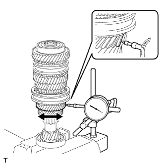
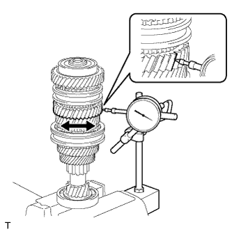
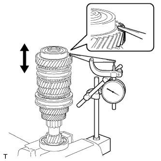
INSPECT 3RD GEAR THRUST CLEARANCE
-
Using a dial indicator, measure the 3rd gear thrust clearance.
Standard clearance 0.20 to 0.47 mm (0.00787 to 0.0185 in.) Maximum clearance 0.47 mm (0.0185 in.) If the clearance is more than the maximum, replace the No. 2 transmission clutch hub, 3rd gear or input shaft. Replace the part or parts determined to be the most likely cause of the problem.
-
-
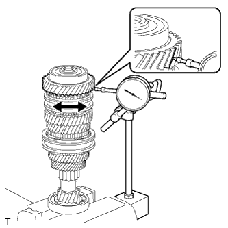
INSPECT 4TH GEAR THRUST CLEARANCE
-
Using a dial indicator, measure the 4th gear thrust clearance.
Standard clearance 0.13 to 0.60 mm (0.00512 to 0.0236 in.) Maximum clearance 0.60 mm (0.0236 in.) If the clearance is more than the maximum, replace the No. 2 transmission clutch hub, 4th gear or input shaft. Replace the part or parts determined to be the most likely cause of the problem.
-
-
INSPECT 5TH GEAR THRUST CLEARANCE
-
Using a dial indicator, measure the 5th gear thrust clearance.
Standard clearance 0.20 to 0.47 mm (0.00787 to 0.0185 in.) Maximum clearance 0.47 mm (0.0185 in.) If the clearance is more than the maximum, replace the No. 3 transmission clutch hub, 5th gear or input shaft. Replace the part or parts determined to be the most likely cause of the problem.
-
-
INSPECT 6TH GEAR THRUST CLEARANCE
-
Using a dial indicator, measure the 6th gear thrust clearance.
Standard clearance 0.20 to 0.47 mm (0.00787 to 0.0185 in.) Maximum clearance 0.47 mm (0.0185 in.) If the clearance is more than the maximum, replace the No. 3 transmission clutch hub, 6th gear or input shaft. Replace the part or parts determined to be the most likely cause of the problem.
-