MANUAL TRANSAXLE UNIT REASSEMBLY

-
INSTALL FRONT DIFFERENTIAL CASE FRONT TAPERED ROLLER BEARING
-
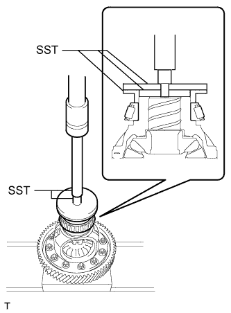
Using SST and a press, press a new front differential case front tapered roller bearing onto the differential case.
- SST
- 09316-20011
- 09950-60010 ( 09951-00580, 09952-06010 )
- 09950-60020 ( 09951-00910 )
- 09950-40011 ( 09957-04010 )
- 09950-70010 ( 09951-07100 )
-
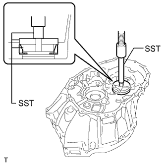
Using SST and a press, press the front differential case front tapered roller bearing (outer race) together with the front differential case front plate washer into the front transaxle case.
- SST
- 09950-60010 ( 09952-06010 )
- 09950-60020 ( 09951-00780, 09951-00890 )
- 09950-70010 ( 09951-07100 )
-
-
INSTALL FRONT DIFFERENTIAL CASE REAR TAPERED ROLLER BEARING
-
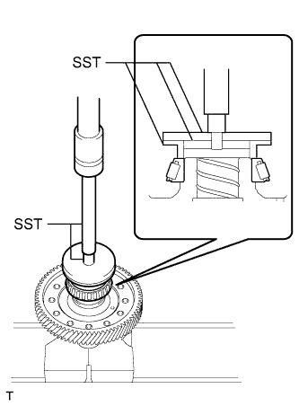
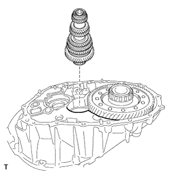
Using SST and a press, press a new front differential case rear tapered roller bearing onto the differential case.
- SST
- 09316-20011
- 09950-60010 ( 09951-00580, 09952-06010 )
- 09950-60020 ( 09951-00910 )
- 09950-40011 ( 09957-04010 )
- 09950-70010 ( 09951-07100 )
-

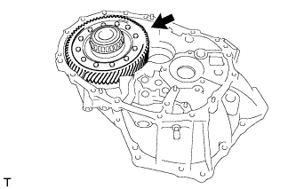
Using SST, install the front differential case rear tapered roller bearing (outer race) together with the front differential case rear plate washer as shown in the illustration.
- SST
- 09950-60020 ( 09951-00770, 09951-00890 )
-
-
ADJUST DIFFERENTIAL SIDE BEARING PRELOAD
-
Coat the differential case assembly with gear oil and install it to the front transaxle case.
-

Install the manual transmission case with the 17 bolts.
- Torque:
- 29 N*m { 300 kgf*cm, 22 ft.*lbf }
-
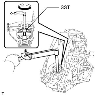
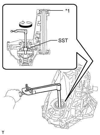
Using SST and a torque wrench, turn the differential case assembly clockwise and counterclockwise 2 or 3 times to allow the bearings to settle.
- SST
- 09564-50010
-
Using SST and a torque wrench, measure the preload.
- SST
- 09564-50010
Standard preload (at starting) New bearing 1.50 to 2.30 N*m (15 to 23 kgf*cm, 13 to 20 in.*lbf) Used bearing 0.24 to 0.37 N*m (2.44 to 3.77 kgf*cm, 2.12 to 3.27 in.*lbf) If the preload is not as specified, replace the front differential case rear shim with one of a different thickness. Use the table below to select a front differential case rear shim which will ensure that the preload is within the specification.
Standard Shim Thickness Mark Specified Condition Mark Specified Condition A 2.05 mm (0.0807 in.) K 2.50 mm (0.0984 in.) B 2.10 mm (0.0827 in.) L 2.55 mm (0.100 in.) C 2.15 mm (0.0846 in.) M 2.60 mm (0.102 in.) D 2.20 mm (0.0866 in.) N 2.65 mm (0.104 in.) E 2.25 mm (0.0886 in.) P 2.70 mm (0.106 in.) F 2.30 mm (0.0906 in.) Q 2.75 mm (0.108 in.) G 2.35 mm (0.0925 in.) R 2.80 mm (0.110 in.) H 2.40 mm (0.0945 in.) S 2.85 mm (0.112 in.) J 2.45 mm (0.0965 in.) T 2.90 mm (0.114 in.) Tech Tips
-
Select a thicker plate washer to increase the preload, or a thinner plate washer to decrease the preload.
-
Make a memo as the torque values will be needed for the Adjust Output Shaft Bearing Preload procedure.
-
Remove the 17 bolts and manual transmission case.
-
Remove the differential case from the front transaxle case.
-
Replace the installed front differential case rear plate washer with the one selected above.
-
-
INSTALL FRONT OUTPUT SHAFT BEARING
-
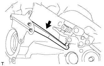
Install the output shaft cover to the front transaxle case.
Note
Insert the output shaft cover key into the case groove.
-
Using SST and a press, press the front output shaft bearing (outer race) into the front transaxle case.
- SST
- 09950-60010 ( 09951-00620, 09952-06010 )
- 09950-60020 ( 09951-00710 )
- 09950-70010 ( 09951-07100 )
-
-
INSTALL REAR OUTPUT SHAFT BEARING
-
Using SST and a press, press the rear output shaft bearing (outer race) together with the rear output shaft bearing shim into the manual transmission case.
- SST
- 09950-60010 ( 09951-00490, 09951-00620, 09952-06010 )
- 09950-70010 ( 09951-07150 )
-
-
ADJUST OUTPUT SHAFT BEARING PRELOAD
-
Coat the differential case assembly with gear oil and install it to the front transaxle case.
-
Coat the output shaft assembly with gear oil and install it to the front transaxle case.
-
Install the manual transmission case with the 17 bolts.
- Torque:
- 29 N*m { 300 kgf*cm, 22 ft.*lbf }
-
Text in Illustration *1 Bearing Shim Using SST and a torque wrench, turn the differential case assembly clockwise and counterclockwise 2 or 3 times to allow the bearings to settle.
- SST
- 09564-50010
-
Using SST and a torque wrench, measure the preload (value A). Calculate the rear output shaft bearing preload using the following formula.
- SST
- 09564-50010
Formula Value A - Differential side bearing preload = Output shaft bearing preload Preload (at starting) New bearing 2.80 to 5.60 N*m (29 to 57 kgf*cm, 25 to 50 in.*lbf) Used bearing 2.31 to 4.62 N*m (24 to 47 kgf*cm, 20 to 41 in.*lbf) If the preload is not as specified, replace the rear output shaft bearing shim with one of a different thickness. Use the table below to select a rear output shaft bearing shim which will ensure that the preload is within the specification.
Standard Bearing Shim Thickness Mark Specified Condition Mark Specified Condition A 1.30 mm (0.511 in.) P 1.95 mm (0.768 in.) B 1.35 mm (0.531 in.) Q 2.00 mm (0.787 in.) C 1.40 mm (0.551 in.) R 2.05 mm (0.807 in.) D 1.45 mm (0.571 in.) S 2.10 mm (0.827 in.) E 1.50 mm (0.591 in.) T 2.15 mm (0.846 in.) F 1.55 mm (0.610 in.) U 2.20 mm (0.866 in.) G 1.60 mm (0.630 in.) V 2.25 mm (0.886 in.) H 1.65 mm (0.650 in.) W 2.30 mm (0.906 in.) J 1.70 mm (0.669 in.) X 2.35 mm (0.925 in.) K 1.75 mm (0.689 in.) Y 2.40 mm (0.945 in.) L 1.80 mm (0.709 in.) Z 2.45 mm (0.965 in.) M 1.85 mm (0.728 in.) 1 2.50 mm (0.984 in.) N 1.90 mm (0.748 in.) - - Tech Tips
Select a thicker bearing shim to increase the preload, or a thinner bearing shim to decrease the preload.
-
Remove the 17 bolts and manual transmission case.
-
Remove the output shaft assembly from the front transaxle case.
-
Remove the differential case from the front transaxle case.
-
Replace the installed rear output shaft bearing shim with the one selected above.
-
-
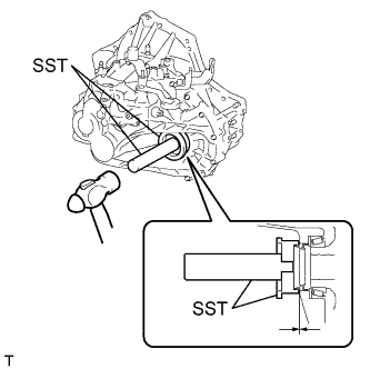
INSTALL OUTER SHIFT LEVER OIL SEAL
-
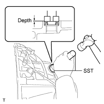
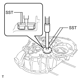
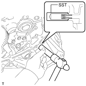
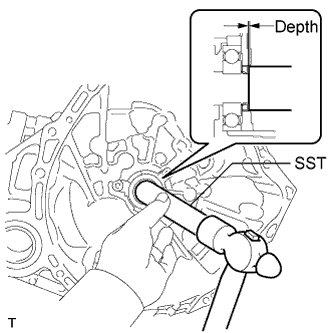
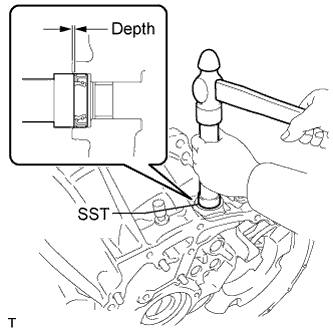
Using SST and a hammer, tap in a new outer shift lever oil seal to the manual transmission case.
- SST
- 09950-60010 ( 09951-00280 )
- 09950-70010 ( 09951-07100 )
Standard depth 0.5 to 1.0 mm (0.0197 to 0.0393 in.) -
Coat the lip of the outer shaft lever oil seal with MP grease.
-
-
INSTALL OUTER NO. 1 SHIFT LEVER
-
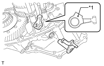
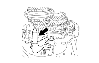
Install the inner No. 1 shift lever, outer shift lever spacer and outer No. 1 shift lever to the manual transmission case.
-
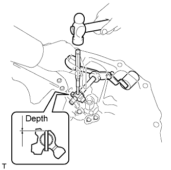
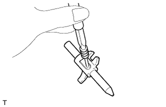
Using a 5 mm pin punch and hammer, tap in the inner shift lever slotted spring pin to the inner No. 1 shift lever.
Standard depth -0.5 to 0.5 mm (-0.0197 to 0.0197 in.)
-
-
INSTALL NO. 1 OIL RECEIVER PIPE
-
Install the No. 1 oil receiver pipe to the manual transmission case.
Tech Tips
Make sure that the No. 1 oil receiver pipe fully contacts the manual transmission case.
-
-
INSTALL STRAIGHT PIN
-
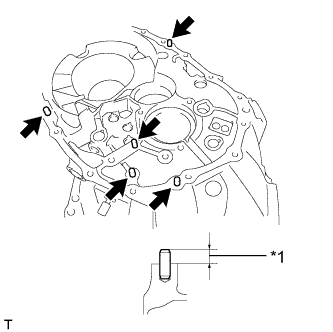
Using a plastic-faced hammer, tap in 5 new straight pins to the specified protrusion height.
Protrusion height 10.5 to 11.5 mm (0.413 to 0.452 in.) Text in Illustration *1 10.5 to 11.5 mm
-
-
INSTALL BREATHER PLUG
-
Using SST and a hammer, tap in the breather plug to the front transaxle case.
- SST
- 09350-30020 ( 09350-07110 )
-
-
INSTALL FRONT TRANSAXLE CASE OIL SEAL
-
Using SST and a hammer, tap in a new front transaxle case oil seal to the front transaxle case.
- SST
- 09612-22011
Standard depth 1.0 to 2.0 mm (0.0393 to 0.0787 in.) -
Coat the lip of the front transaxle case oil seal with MP grease.
-
-
INSTALL TRANSMISSION MAGNET
-
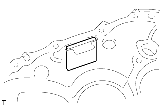
Clean the transmission magnet and install it to the front transaxle case.
-
-
INSTALL INPUT SHAFT COVER
-
Install the input shaft cover to the manual transmission case.
Note
Insert the input shaft cover key into the manual transmission case groove.
-
-
INSTALL REAR INPUT SHAFT BEARING SHIM
-
Install the rear input shaft bearing shim onto the manual transmission case.
Note
Apply grease allowed on shim, (to avoid) falling shim off, from case during assembly.
-
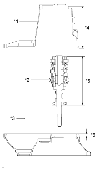
Text in Illustration *1 Manual Transmission Case *2 Input Shaft Assembly *3 Front Transaxle Case *4 Dimension A *5 Dimension C *6 Dimension B Measure the distance between the end of the manual transmission case and rear input shaft bearing shim (Dimension A).
-
Measure the distance between the end of the front transaxle case and installation surface of the front input shaft bearing (Dimension B).
-
Measure the distance between both input shaft bearing outer races (Dimension C).
Note
Measure Dimension C with each bearing having no axial clearance.
-
Calculate the rear input shaft bearing shim clearance using the following formula.
Formula (Dimension A + Dimension B) - Dimension C - Rear input shaft bearing shim thickness = Between 0 mm and 0.1 mm (0.00394 in.) If the clearance is not as specified, replace the rear input shaft bearing shim with one of a different thickness. Use the table below to select a rear input shaft bearing shim which will ensure that the clearance is within the specification.
Standard Rear Input Shaft Bearing Shim Thickness Mark Specified Condition Mark Specified Condition A 1.15 mm (0.0453 in.) H 1.50 mm (0.0591 in.) B 1.20 mm (0.0472 in.) J 1.55 mm (0.0610 in.) C 1.25 mm (0.0492 in.) K 1.60 mm (0.0630 in.) D 1.30 mm (0.0512 in.) L 1.65 mm (0.0650 in.) E 1.35 mm (0.0531 in.) M 1.70 mm (0.0669 in.) F 1.40 mm (0.0551 in.) N 1.75 mm (0.0689 in.) G 1.45 mm (0.0571 in.) P 1.80 mm (0.0709 in.) -
Coat the selected rear input shaft bearing shim with MP grease, and then replace the installed rear input shaft bearing shim with the one selected above.
Note
Apply grease to the shim to prevent it from falling off the case during assembly.
-
-
INSTALL DIFFERENTIAL CASE ASSEMBLY
-
Coat the differential case tapered roller bearing with gear oil and install it to the front transaxle case.
-
-
INSTALL INPUT SHAFT ASSEMBLY
-
Apply gear oil to all sliding and rotating parts.
-
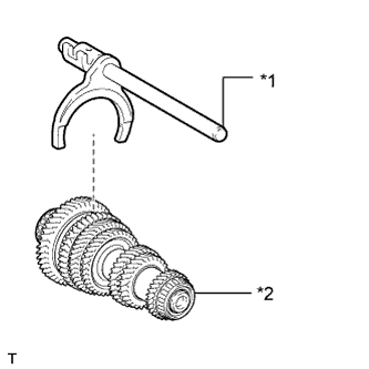
Text in Illustration *1 No. 1 Gear Shift Fork Shaft *2 Output Shaft Coat the No. 1 gear shift fork shaft with gear oil and install it onto the output shaft assembly.
-
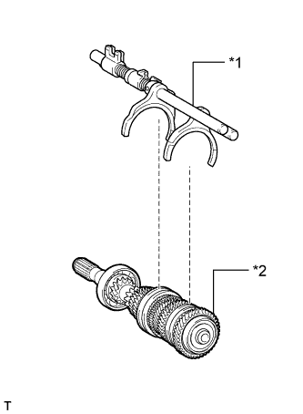
Text in Illustration *1 No. 2 Gear Shift Fork Shaft *2 Input Shaft Coat the No. 2 gear shift fork shaft with gear oil and install it onto the input shaft assembly.
-
Temporarily install the output shaft with No. 1 gear shift fork shaft to the input shaft assembly, and tie them with a rope or string.
-
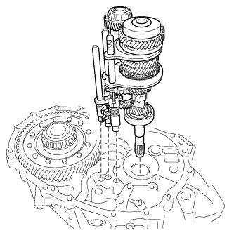
Install the input shaft assembly, output shaft assembly and 2 gear shift fork shaft assemblies to the front transaxle case.
-
-
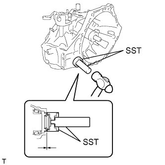
INSTALL OUTER SELECT LEVER OIL SEAL
-
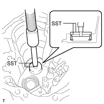
Using SST and a hammer, tap in a new oil seal to the front transaxle case.
- SST
- 09950-60010 ( 09951-00250 )
- 09950-70010 ( 09951-07100 )
Standard depth 0.5 to 1.0 mm (0.0197 to 0.0393 in.) -
Coat the lip of the outer select lever oil seal with MP grease.
-
-
INSTALL OUTER SELECT LEVER
-
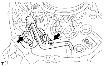
Text in Illustration *1 Mark Install the outer select lever and inner select lever to the front transaxle case.
Tech Tips
Install the lever with its mark positioned outside of the front transaxle case.
-
Coat the threads of the inner select lever bolt with adhesive and install it.
Adhesive Toyota Genuine Adhesive 1344, Three Bond 1344 or equivalent - Torque:
- 38 N*m { 387 kgf*cm, 28 ft.*lbf }
-
-
INSTALL SHIFT AND SELECT LEVER SHAFT ASSEMBLY
-
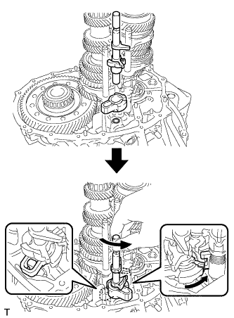
Install the shift interlock plate and shift and select lever shaft assembly to the front transaxle case, and then turn them counterclockwise.
Tech Tips
When installing the shift interlock plate, make sure to engage it with the inner select lever.
-
-
INSTALL REVERSE SHIFT ARM BRACKET ASSEMBLY
-
Coat the threads of the 2 bolts with adhesive, and then install the reverse shift arm bracket with the 2 bolts.
Adhesive Toyota Genuine Adhesive 1344, Three Bond 1344 or equivalent - Torque:
- 17 N*m { 175 kgf*cm, 13 ft.*lbf }
-
-
INSTALL REVERSE SHIFT FORK
-
Using a pin punch 5 mm and a hammer, install the reverse shift fork slotted pin onto the reverse shift fork shaft.
Standard depth -0.5 to 1.0 mm (-0.0197 to 0.03934 in.) Note
Confirm the installation direction.
-
-
INSTALL REVERSE SHIFT FORK SHAFT ASSEMBLY
-
Coat the reverse shift fork shaft assembly with gear oil and install it onto the front transaxle case.
-
-
INSTALL REVERSE IDLER GEAR SUB-ASSEMBLY
-
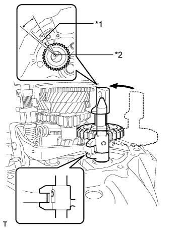
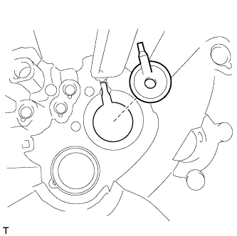
Text in Illustration *1 Case Hole *2 I-groove mark of the reverse idler gear shaft Coat the reverse idler gear sub-assembly, thrust washer and reverse idler gear shaft with gear oil, and install them as shown in the illustration.
Note
Using the bolt hole of the case for reference, align the I-groove mark of the reverse idler gear shaft within the range shown (approximately 20°).
Tech Tips
Raise the edge of the reverse shift arm bracket assembly and connect the reverse shift arm bracket assembly to the reverse shift fork shaft assembly.
-
-
INSTALL MANUAL TRANSMISSION CASE
-
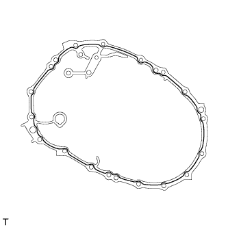
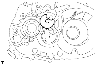
Apply seal packing to the manual transmission case as shown in the illustration.
Seal packing Toyota Genuine Seal Packing 1281, Three Bond 1281 or equivalent Seal packing diameter 1.2 mm (0.0472 in.) Note
-
Remove any oil from the contact surfaces.
-
Assemble the parts within 10 minutes of application. Otherwise, the packing (FIPG) material must be removed and reapplied.
-
-
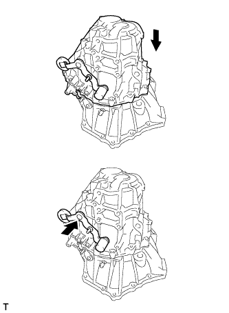
Push the outer No. 1 shift lever and install the manual transmission case.
Tech Tips
Pushing the outer No. 1 shift lever allows the manual transmission case to be installed.
-
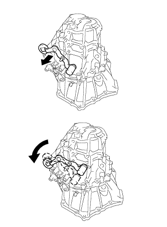
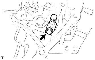
Turn the outer No. 1 shift lever counterclockwise and then pull it.
-
Install the manual transmission case with the 17 bolts.
- Torque:
- 29 N*m { 300 kgf*cm, 22 ft.*lbf }
-
-
INSTALL OUTER SHIFT LEVER E-RING
-
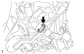
Install the outer shift lever E-ring to the outer No. 1 shift lever.
-
-
INSTALL TRANSMISSION CASE OIL SEAL
-
for LH side:
-
Using SST and a hammer, tap in a new transmission case oil seal to the manual transmission case.
- SST
- 09608-32010
- 09950-70010 ( 09951-07100 )
Standard depth -0.5 to 0.5 mm (-0.0197 to 0.0197 in.) Note
Do not damage the oil seal lip.
-
Coat the lip of the transmission case oil seal with MP grease.
-
-
for RH side:
-
Using SST and a hammer, tap in a new transmission case oil seal to the front transaxle case.
- SST
- 09710-30050
- 09950-70010 ( 09951-07100 )
Standard depth -0.5 to 0.5 mm (-0.0197 to 0.0197 in.) Note
Do not damage the oil seal lip.
-
Coat the lip of the transmission case oil seal with MP grease.
-
-
-
INSTALL SHIFT DETENT BALL
-
Install the 2 shift detent balls and 2 compression springs to the manual transmission case.
Note
Be careful not to drop the ball into the manual transmission case.
-
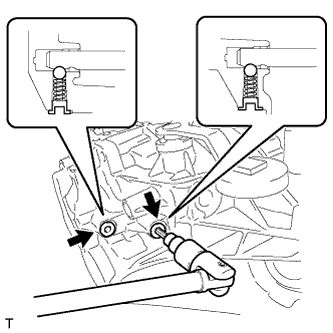
Coat the threads of the 2 shift detent ball plugs with adhesive and install them using a 6 mm hexagon socket wrench.
Adhesive Toyota Genuine Adhesive 1344, Three Bond 1344 or equivalent - Torque:
- 22 N*m { 224 kgf*cm, 16 ft.*lbf }
-
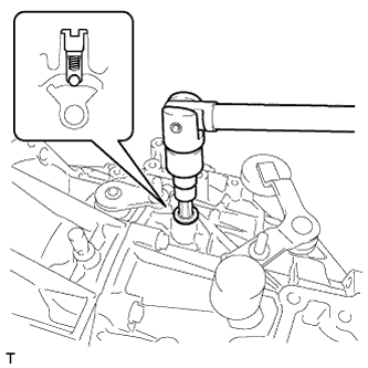
Install the shift detent ball and compression spring to the manual transmission case.
Note
Be careful not to drop the lock ball pin into the manual transmission case.
-
Coat the threads of the shift detent ball plug with adhesive and install it using a 6 mm hexagon socket wrench.
Adhesive Toyota Genuine Adhesive 1344, Three Bond 1344 or equivalent - Torque:
- 22 N*m { 224 kgf*cm, 16 ft.*lbf }
-
-
INSTALL LOCK BALL PIN
-
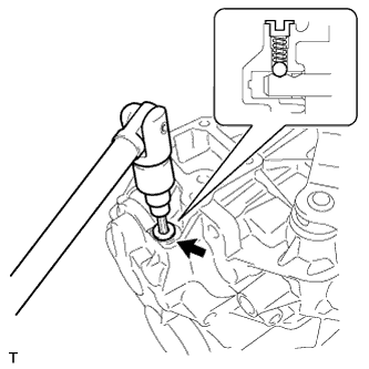
Install the lock ball pin and compression spring to the manual transmission case.
Note
Be careful not to drop the lock ball pin into the manual transmission case.
-
Coat the threads of the plug with adhesive and install it using a 10 mm hexagon socket wrench.
Adhesive Toyota Genuine Adhesive 1344, Three Bond 1344 or equivalent - Torque:
- 25 N*m { 250 kgf*cm, 18 ft.*lbf }
-
Install the lock ball pin and compression spring to the manual transmission case.
Note
Be careful not to drop the lock ball pin into the manual transmission case.
-
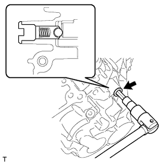
Coat the threads of the plug with adhesive and install it using a 10 mm hexagon socket wrench.
Adhesive Toyota Genuine Adhesive 1344, Three Bond 1344 or equivalent - Torque:
- 25 N*m { 250 kgf*cm, 18 ft.*lbf }
-
-
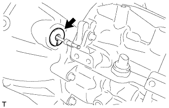
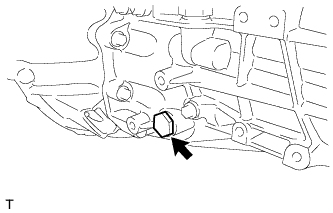
INSTALL REVERSE IDLER GEAR SHAFT BOLT
-
Install a new gasket and the reverse idler gear shaft bolt to the manual transmission case.
- Torque:
- 30 N*m { 306 kgf*cm, 22 ft.*lbf }
-
-
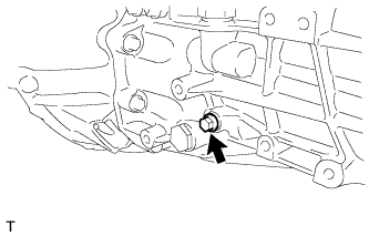
INSTALL RELEASE CYLINDER BLEEDER PLUG
-
Install the release cylinder bleeder plug to the clutch release bleeder.
- Torque:
- 8.4 N*m { 86 kgf*cm, 74 in.*lbf }
-
-
INSTALL RELEASE CYLINDER BLEEDER PLUG CAP
-
Install the release cylinder bleeder plug cap to the release cylinder bleeder plug.
-
-
INSTALL CLUTCH RELEASE WITH BEARING CYLINDER ASSEMBLY
-
Temporarily install the clutch release cylinder to bleeder tube to a new clutch release with bearing cylinder assembly.
-
Clean and degrease all installation surfaces for the clutch release with bearing cylinder assembly.
-
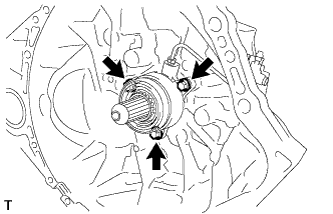
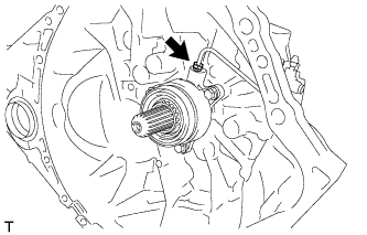
Install the clutch release with bearing cylinder assembly with 3 new bolts.
- Torque:
- 23 N*m { 229 kgf*cm, 17 ft.*lbf }
Note
-
The clutch release with bearing cylinder and installation bolts cannot be reused and must be replaced with new ones.
-
Clean and degrease all installation surfaces and make sure the clutch release with bearing cylinder fits securely with the transaxle during installation. The first bolt should be tightened by hand while holding the clutch release with bearing cylinder.
-
Make sure that none of the clutch spline grease adheres to the clutch release with bearing cylinder.
-
The clutch release with bearing cylinder cannot be disassembled.
-
Install the clutch tube boot to the manual transaxle assembly.
-
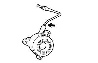
Temporarily install the clutch release cylinder to bleeder tube to the clutch release bleeder sub-assembly.
-
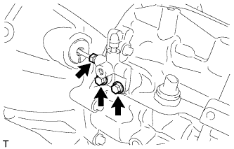
Temporarily install the clutch release bleeder sub-assembly with the 2 bolts.
-
Using a union nut wrench, install the clutch release cylinder to bleeder tube.
- Torque:
- 15 N*m { 155 kgf*cm, 11 ft.*lbf }
Note
Use the formula to calculate special torque values for situations where a union nut wrench is combined with a torque wrench Click here.
-
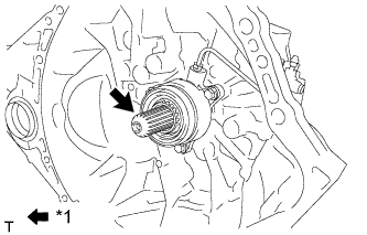
Text in Illustration *1 Clutch spline grease Apply clutch spline grease to the input shaft spline.
Grease Toyota Genuine Clutch Spline Grease or equivalent
-
-
INSTALL CLUTCH RELEASE BLEEDER SUB-ASSEMBLY
-
Temporarily install the clutch release cylinder to bleeder tube to the clutch release bleeder sub-assembly.
-
Install the clutch release bleeder sub-assembly with the 2 bolts.
- Torque:
- 17 N*m { 170 kgf*cm, 12 ft.*lbf }
-
Using a union nut wrench, install the clutch release cylinder to bleeder tube.
- Torque:
- 15 N*m { 155 kgf*cm, 11 ft.*lbf }
Note
Use the formula to calculate special torque values for situations where a union nut wrench is combined with a torque wrench Click here.
-
-
INSTALL CLUTCH RELEASE CYLINDER TO BLEEDER TUBE
-
Using a union nut wrench, install the clutch release bleeder tube.
- Torque:
- 15 N*m { 155 kgf*cm, 11 ft.*lbf }
Note
Use the formula to calculate special torque values for situations where a union nut wrench is combined with a torque wrench Click here.
-
-
INSPECT CLUTCH PIPE LINE
-
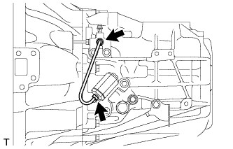
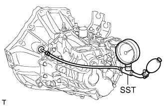
Using SST, apply a pressure of 100 kPa (1.0 kgf/cm2, 15 psi) to the clutch pipe location shown in the illustration and confirm that pressure is maintained for 15 seconds or more.
- SST
- 09992-00242
If the pressure drops, replace the clutch release cylinder to bleeder tube.
-
-
INSTALL CONTROL CABLE BRACKET ASSEMBLY
-
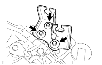
Install the control cable bracket to the manual transmission case with the 3 bolts.
- Torque:
- 17 N*m { 173 kgf*cm, 13 ft.*lbf }
-
-
INSTALL NEUTRAL POSITION SWITCH
-
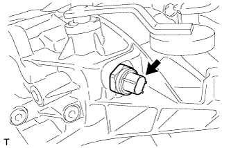
Using a 27 mm deep socket wrench, install a new gasket and the neutral position switch to the manual transmission case.
- Torque:
- 40 N*m { 410 kgf*cm, 30 ft.*lbf }
-
-
INSTALL BACK-UP LIGHT SWITCH ASSEMBLY
-
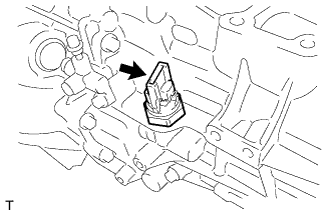
Using a 27 mm deep socket wrench, install a new gasket and the back-up light switch to the manual transmission case.
- Torque:
- 40 N*m { 410 kgf*cm, 30 ft.*lbf }
-
-
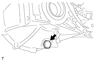
INSTALL MANUAL TRANSMISSION FILLER PLUG
-
Install a new gasket and the manual transmission filler plug to the manual transmission case.
- Torque:
- 39 N*m { 400 kgf*cm, 29 ft.*lbf }
-
-
INSTALL MANUAL TRANSMISSION DRAIN PLUG
-
Install a new gasket and the manual transmission drain plug to the front transaxle case.
- Torque:
- 39 N*m { 400 kgf*cm, 29 ft.*lbf }
-