TRANSMISSION CONTROL CABLE INSTALLATION

-
INSTALL TRANSMISSION CONTROL CABLE ASSEMBLY
-
Install the control cable assembly through the floor hole.
-
Attach the 2 claws to connect the shift control cable and select control cable to the floor shift lever assembly.
-
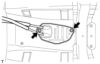
Attach the grommet of the control cable assembly with the 2 nuts.
- Torque:
- 5.0 N*m { 51 kgf*cm, 44 in.*lbf }
-
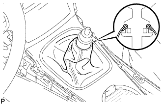
Connect the end of the shift control cable to the shift lever assembly and install the clip.
-
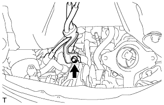
Attach the bracket of the control cable assembly with the bolt.
- Torque:
- 5.0 N*m { 51 kgf*cm, 44 in.*lbf }
-
Connect the 2 cables to the control cable bracket with 2 new clips.
-
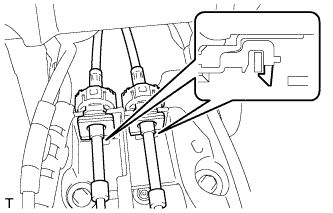
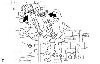
Connect the 2 cables to the transaxle and install the 2 clips.
-
Release the lock of the cable length adjustment structure of the select cable.
-
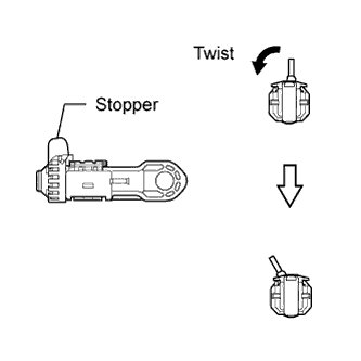
Twist the stopper.
-
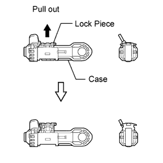
Pull the lock piece outward from the case to release the lock.
-
-
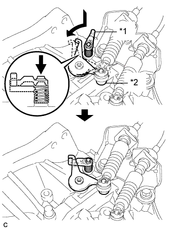
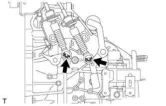
Text in Illustration *1 Reverse Restrict Pin Assembly *2 Outer Lever Hook the outer lever of the manual transaxle onto the reverse restrict pin assembly to secure it.
-
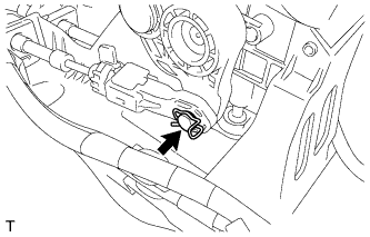
Connect the end of the select control cable to the shift lever assembly and install the clip.
Note
-
Make sure the lock piece of the select control cable is facing upward when the select control cable is connected.
-
Make sure the clip is inserted in the direction shown in the illustration.
-
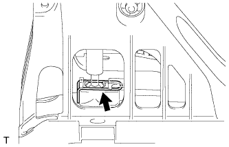
-
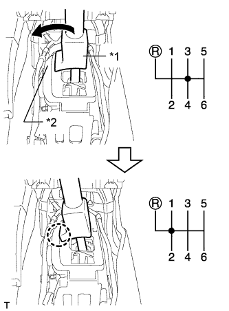
Text in Illustration *1 Slider *2 Inhibitor Wall Push the slider against the inhibitor wall.
Note
-
Do not pull up the slider.
-
When adjusting the cable, make sure that the shift lever is not in 1 or 2.
-
-
Lock the cable length adjustment structure of the select cable.
-
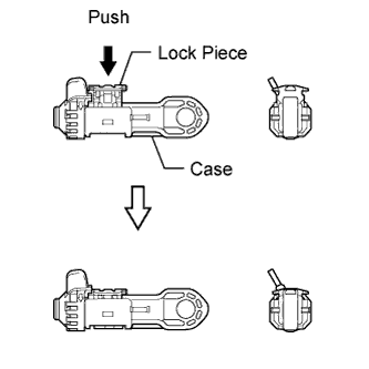
Push the lock piece into the case with the slider held against the inhibitor wall.
-
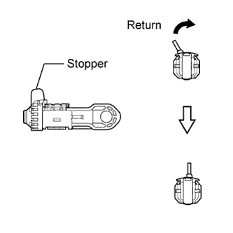
Return the stopper to prevent the lock from being released.
Note
-
Push in the lock piece completely.
-
Make sure that the cable length adjustment structure is locked securely.
-
-
-
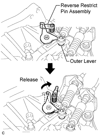
Move the shift lever to R to release the outer lever.
-
-
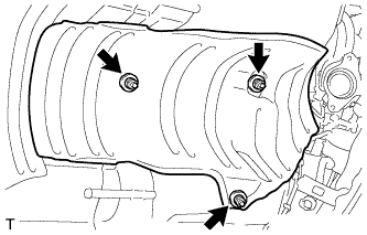
INSTALL FRONT NO. 1 FLOOR HEAT INSULATOR
-
Install the front No. 1 floor heat insulator with the 3 nuts.
- Torque:
- 5.5 N*m { 56 kgf*cm, 49 in.*lbf }
-
-
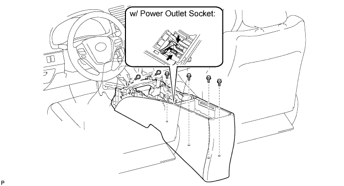
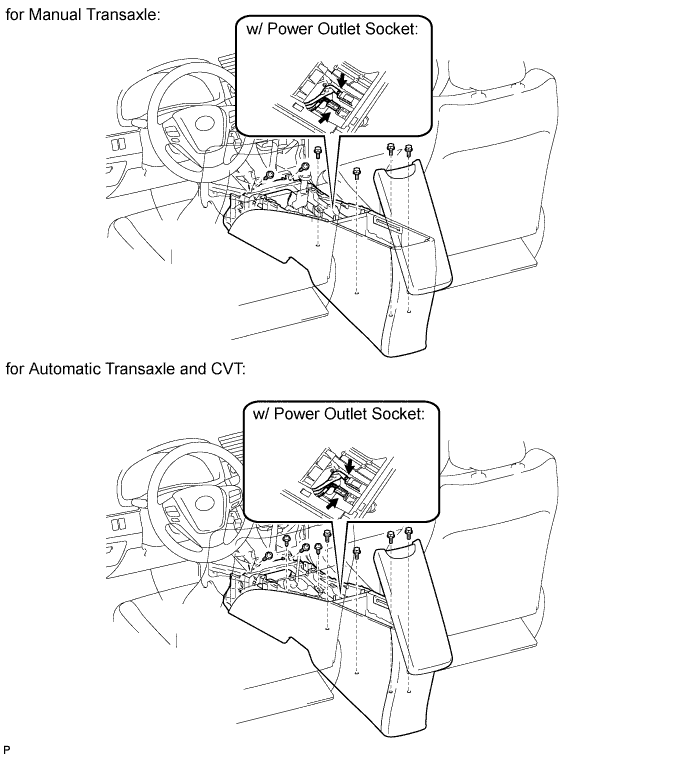
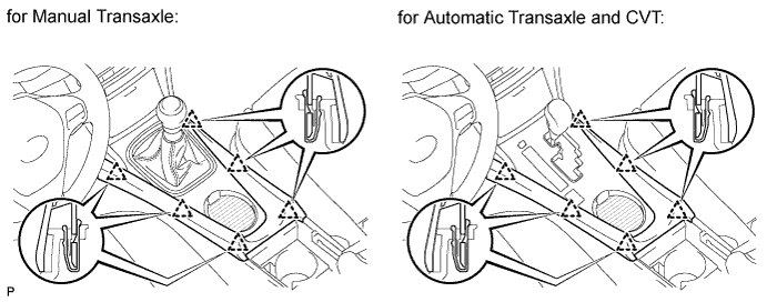
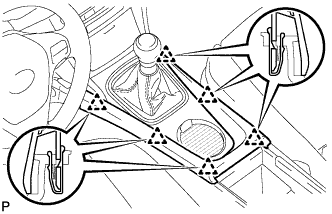
INSTALL CONSOLE BOX ASSEMBLY (w/o Console Box Lid)
-
Install the console box with the 2 screws.
-
w/ Power Outlet Socket:
-
Connect the connectors.
-
-
Install the 4 bolts.
-
-
INSTALL CONSOLE BOX ASSEMBLY (w/ Console Box Lid)
-
for Manual Transaxle:
-
Install the console box with the 2 screws.
-
-
for Automatic Transaxle and CVT:
-
Install the console box with the 4 screws.
-
-
w/ Power Outlet Socket:
-
Connect the connectors.
-
-
Install the 4 bolts.
-
-
INSTALL CONSOLE BOX CARPET (w/o Console Box Lid)
-
Install the 3 carpets.
-
-
INSTALL CONSOLE BOX CARPET (w/ Console Box Lid)
-
Install the 2 carpets.
-
-
INSTALL REAR CONSOLE BOX CUP HOLDER (w/ Console Box Lid)
-
Install the cup holder.
-
-
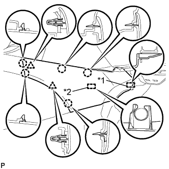
INSTALL REAR UPPER CONSOLE PANEL SUB-ASSEMBLY
-
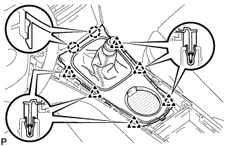
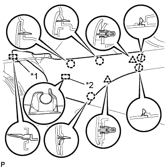
Attach the 2 claws and 6 clips to install the console panel.
-
Attach the cover to the shaft.
-
-
INSTALL SHIFT LEVER KNOB SUB-ASSEMBLY
-
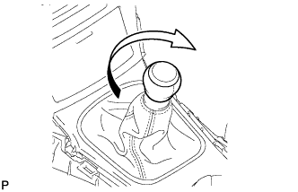
Install the shift lever knob and twist it in the direction indicated by the arrow.
-
-
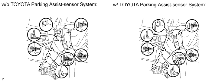
INSTALL INSTRUMENT PANEL FINISH PANEL END RH (for RHD)
-
w/o TOYOTA Parking Assist-sensor System:
-
Attach the 4 clips and 5 claws to install the panel end.
-
-
w/ TOYOTA Parking Assist-sensor System:
-
Connect the connector.
-
Attach the 4 clips and 5 claws to install the panel end.
-
-
-
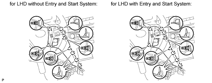
INSTALL INSTRUMENT PANEL FINISH PANEL END RH (for LHD)
-
Attach the 4 clips and 5 claws to install the panel end.
-
-
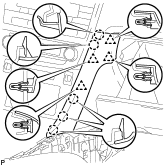
INSTALL INSTRUMENT PANEL FINISH PANEL END LH
-
Attach the 4 clips and 5 claws to install the panel end.
-
-
INSTALL NO. 3 BOX PANEL (w/ Console Box Lid)
-
When replacing the No. 3 box panel with a new one:
-
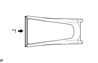
Text in Illustration *1 Cut Cut off the rib (the piece used to maintain the shape of the panel) shown in the illustration.
-
-
Attach the 6 clips to install the box panel.
-
-
INSTALL NO. 3 BOX PANEL (w/o Console Box Lid)
-
When replacing the No. 3 box panel with a new one:
-
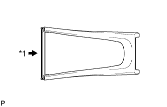
Text in Illustration *1 Cut Cut off the rib (the piece used to maintain the shape of the panel) shown in the illustration.
-
-
Attach the 6 clips to install the box panel.
-
-
INSTALL LOWER NO. 1 INSTRUMENT PANEL FINISH PANEL
-
Text in Illustration *1 Guide *2 Clamp Attach the guide near the front of the vehicle.
-
Attach the clamp.
-
Attach the 2 clips and 5 claws to install the finish panel.
-
-
INSTALL LOWER NO. 2 INSTRUMENT PANEL FINISH PANEL
-
Text in Illustration *1 Guide *2 Clamp Attach the guide near the front of the vehicle.
-
Attach the clamp.
-
Attach the 2 clips and 5 claws to install the finish panel.
-
-
INSTALL AIR CLEANER CASE SUB-ASSEMBLY
-
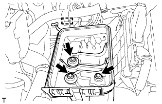
Install the air cleaner case with the 3 bolts.
- Torque:
- 7.0 N*m { 71 kgf*cm, 62 in.*lbf }
-
Attach the wire harness clamp to the air cleaner case.
-
-
INSTALL AIR CLEANER CAP SUB-ASSEMBLY
-
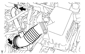
Connect the air cleaner cap with the band.
-
Connect the ventilation hose.
-
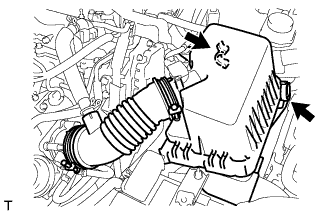
Connect the 2 clamps.
-
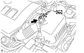
Attach the wire harness to the 2 clamps.
-
Connect the mass air flow meter connector.
-
-
INSTALL NO. 2 CYLINDER HEAD COVER
-
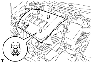
Attach the 4 clips to install the cover.
Note
-
Be sure to attach the clips securely.
-
Do not apply excessive force or hit the cover to attach the clips. This may cause the cover to break.
-
-
-
INSTALL FRONT EXHAUST PIPE ASSEMBLY
-
Install the front exhaust pipe assembly Click here.
-