CLUTCH PEDAL (for LHD) INSTALLATION

-
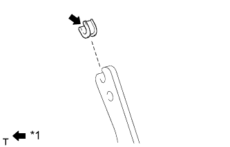
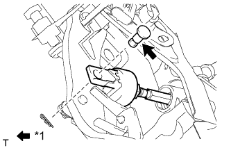
INSTALL CLUTCH PEDAL TURNOVER BUSH (except 1ZR-FAE)
Text in Illustration *1 MP grease
-
Install the clutch pedal turnover bush to the clutch pedal sub-assembly.
-
Apply MP grease to the inside of the clutch pedal turnover bush.
-
-
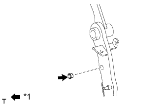
INSTALL CLUTCH MASTER CYLINDER PUSH ROD CLEVIS BUSHING
Text in Illustration *1 MP grease
-
Apply MP grease to the inside of a new clutch master cylinder push rod clevis bushing.
-
Install the clutch master cylinder push rod clevis bushing to the clutch pedal sub-assembly.
Tech Tips
Install the clutch master cylinder push rod clevis bushing from the left side of the vehicle.
-
-
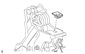
INSTALL NO. 1 CLUTCH PEDAL CUSHION
-
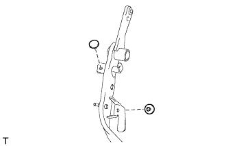
Install the 2 No. 1 clutch pedal cushions to the clutch pedal sub-assembly.
-
-
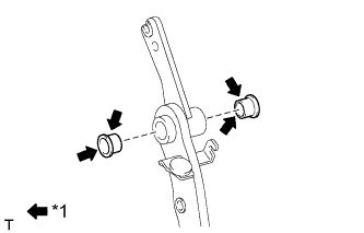
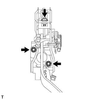
INSTALL CLUTCH PEDAL BUSHING
Text in Illustration *1 MP grease
-
Apply MP grease to both sides of 2 new clutch pedal bushings.
-
Install the 2 clutch pedal bushings to the clutch pedal sub-assembly.
-
-
INSTALL CLUTCH PEDAL PAD
-
Install the clutch pedal pad to the clutch pedal sub-assembly.
-
-
INSTALL CLUTCH PEDAL SUB-ASSEMBLY
-
Install the clutch pedal sub-assembly to the clutch pedal support sub-assembly with the bolt and nut.
- Torque:
- 37 N*m { 375 kgf*cm, 27 ft.*lbf }
Tech Tips
Install the bolt from the right side of the vehicle.
-
-
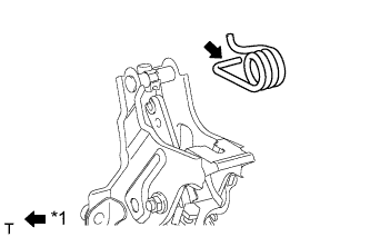
INSTALL CLUTCH PEDAL SPRING (for 1ZR-FAE)
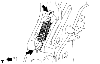
Text in Illustration *1 MP grease
-
Apply MP grease to the sliding portions of the clutch pedal spring.
-
Install the clutch pedal spring.
-
-
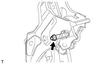
INSTALL CLUTCH PEDAL STOPPER BOLT
-
Install the clutch pedal stopper bolt together with the nut so that its end touches the No. 1 clutch pedal cushion.
Tech Tips
Tighten the lock nut to the specified torque when adjusting the clutch pedal.
-
-
INSTALL CLUTCH PEDAL SPRING HOLDER (except 1ZR-FAE)
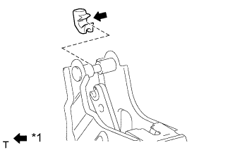
Text in Illustration *1 MP grease
-
Apply MP grease to the contact surface of the clutch pedal spring holder.
-
Install the clutch pedal spring holder to the clutch pedal support sub-assembly.
-
-
INSTALL TURN OVER SPRING SEAT COMPRESSION SPRING (except 1ZR-FAE)
Text in Illustration *1 MP grease
-
Apply MP grease to the contact surfaces of the clutch pedal and turn over seat compression spring.
-
Install the turn over seat compression spring to the clutch pedal and clutch pedal spring holder.
-
-
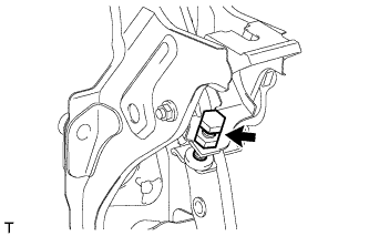
INSTALL CLUTCH START SWITCH ASSEMBLY
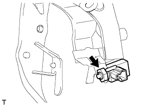
-
Install the clutch start switch assembly with the nut.
- Torque:
- 16 N*m { 160 kgf*cm, 12 ft.*lbf }
-
-
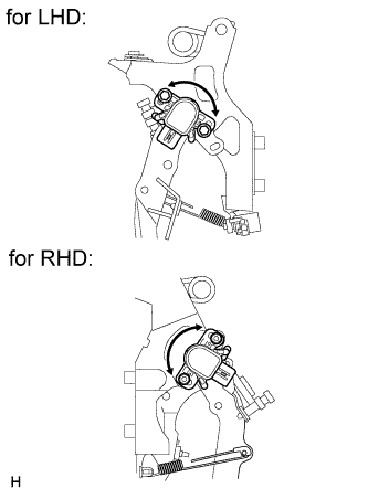
INSTALL BRAKE PEDAL STROKE SENSOR ASSEMBLY (CLUTCH PEDAL STROKE SENSOR)
Note
Do not drop the sensor. If the sensor has been dropped, replace the sensor with a new one.
-
When installing a new brake pedal stroke sensor assembly (clutch pedal stroke sensor):
Note
Do not break the sensor lever set pin before installing the brake pedal stroke sensor (clutch pedal stroke sensor) with the bolts. If the sensor lever set pin breaks while tightening the bolt, do not use that sensor.
-
Connect the sensor connector.
-
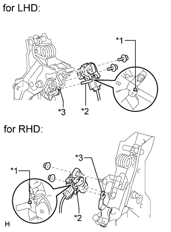
for LHD:
Install a new sensor with the 2 bolts.
Text in Illustration *1 Pin *2 Lever *3 Groove - Torque:
- 8.5 N*m { 87 kgf*cm, 75 in.*lbf }
Note
-
Engage the sensor lever with the clutch pedal groove.
-
Check that there is no foreign matter attached to the contact surface of the sensor.
-
Check that the tip of the sensor lever is protruding from the clutch pedal groove.
-
for RHD:
Install a new sensor with the 2 nuts.
Text in Illustration *1 Pin *2 Lever *3 Groove - Torque:
- 8.5 N*m { 87 kgf*cm, 75 in.*lbf }
Note
-
Engage the sensor lever with the clutch pedal groove.
-
Check that there is no foreign matter attached to the contact surface of the sensor.
-
Check that the tip of the sensor lever is protruding from the clutch pedal groove.
-
Firmly depress the clutch pedal and break the pin.
-
Remove the broken pin.
-
-
When reusing the brake pedal stroke sensor assembly (clutch pedal stroke sensor):
-
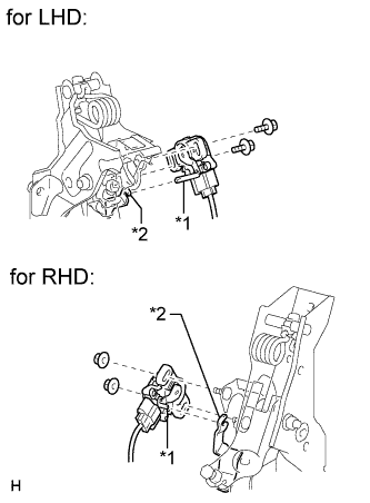
Text in Illustration *1 Lever *2 Groove Connect the sensor connector.
Note
Do not drop the sensor. If the sensor has been dropped, replace the sensor with a new one.
-
for LHD:
Temporarily install the sensor with the 2 bolts.
Note
-
Engage the sensor lever with the clutch pedal groove.
-
Check that there is no foreign matter attached to the contact surface of the sensor.
-
-
for RHD:
Temporarily install the sensor with the 2 nuts.
Note
-
Engage the sensor lever with the clutch pedal groove.
-
Check that there is no foreign matter attached to the contact surface of the sensor.
-
-
Connect the cable to the negative battery terminal.
-
Connect the intelligent tester to the DLC3.
-
Turn the ignition switch to ON.
-
Turn the intelligent tester on.
-
Enter the following menus: Chassis / Electric Parking Brake / Data List.
-
Text in Illustration *1 Lever *2 Groove While reading the value of the stroke sensor shown in the Data List, turn the sensor slowly to the right and left to adjust the output voltage to the standard voltage.
Standard Voltage Tester Display Measurement Item/Range Normal Condition Diagnostic Note SKS1 Raw Value of AD Brake pedal stroke sensor (Clutch pedal stroke sensor)(SKS1) voltage display /
Min.: 0 V
Max.: 5 V
When clutch pedal is released: 0.8 to 1.2 V - -
for LHD:
Tighten the 2 bolts.
- Torque:
- 8.5 N*m { 87 kgf*cm, 75 in.*lbf }
Note
Do not depress the clutch pedal after turning the ignition switch to ON.
-
for RHD:
Tighten the 2 nuts.
- Torque:
- 8.5 N*m { 87 kgf*cm, 75 in.*lbf }
Note
Do not depress the clutch pedal after turning the ignition switch to ON.
-
Turn the ignition switch off.
-
Disconnect the cable from the negative battery terminal.
-
Disconnect the intelligent tester.
-
-
-
INSTALL CLUTCH PEDAL SUPPORT SUB-ASSEMBLY
-
Install the nut to the clutch pedal support sub-assembly.
-
Install the clutch pedal support sub-assembly with the 2 nuts and bolt.
- Torque:
- for bolt
- 24 N*m { 241 kgf*cm, 17 ft.*lbf }
- for nut
- 18 N*m { 178 kgf*cm, 13 ft.*lbf }
-
Connect the clutch start switch assembly connector and brake pedal stroke sensor assembly connector.
-
-
INSTALL CLUTCH MASTER CYLINDER PUSH ROD CLEVIS WITH HOLE PIN
Text in Illustration *1 MP grease
-
Apply MP grease to the contact surface of the clutch master cylinder push rod clevis with hole pin.
-
Connect the clevis to the clutch pedal sub-assembly with the clutch master cylinder push rod clevis with hole pin.
Tech Tips
Install the clutch master cylinder push rod clevis with hole pin from the right side of the vehicle.
-
Install the clip to the clutch master cylinder push rod clevis with hole pin.
-
-
INSPECT AND ADJUST CLUTCH PEDAL SUB-ASSEMBLY
-
Inspect and adjust the clutch pedal sub-assembly Click here.
-
-
INSTALL LOWER NO. 1 INSTRUMENT PANEL AIRBAG ASSEMBLY
-
Install the lower No. 1 instrument panel airbag assembly Click here.
-
-
INSTALL UPPER INSTRUMENT PANEL SUB-ASSEMBLY
-
Install the upper instrument panel sub-assembly Click here.
-
-
PERFORM CLUTCH ENGAGEMENT POINT LEARNING